Rockwell Automation Publication MOTION-UM002E-EN-P - June 2016 85
Configure an Articulated Independent Robot Chapter 4
The internal Kinematic equations are written as if the start position for the
SCARA Independent robot joints are as shown in Figure 35
.
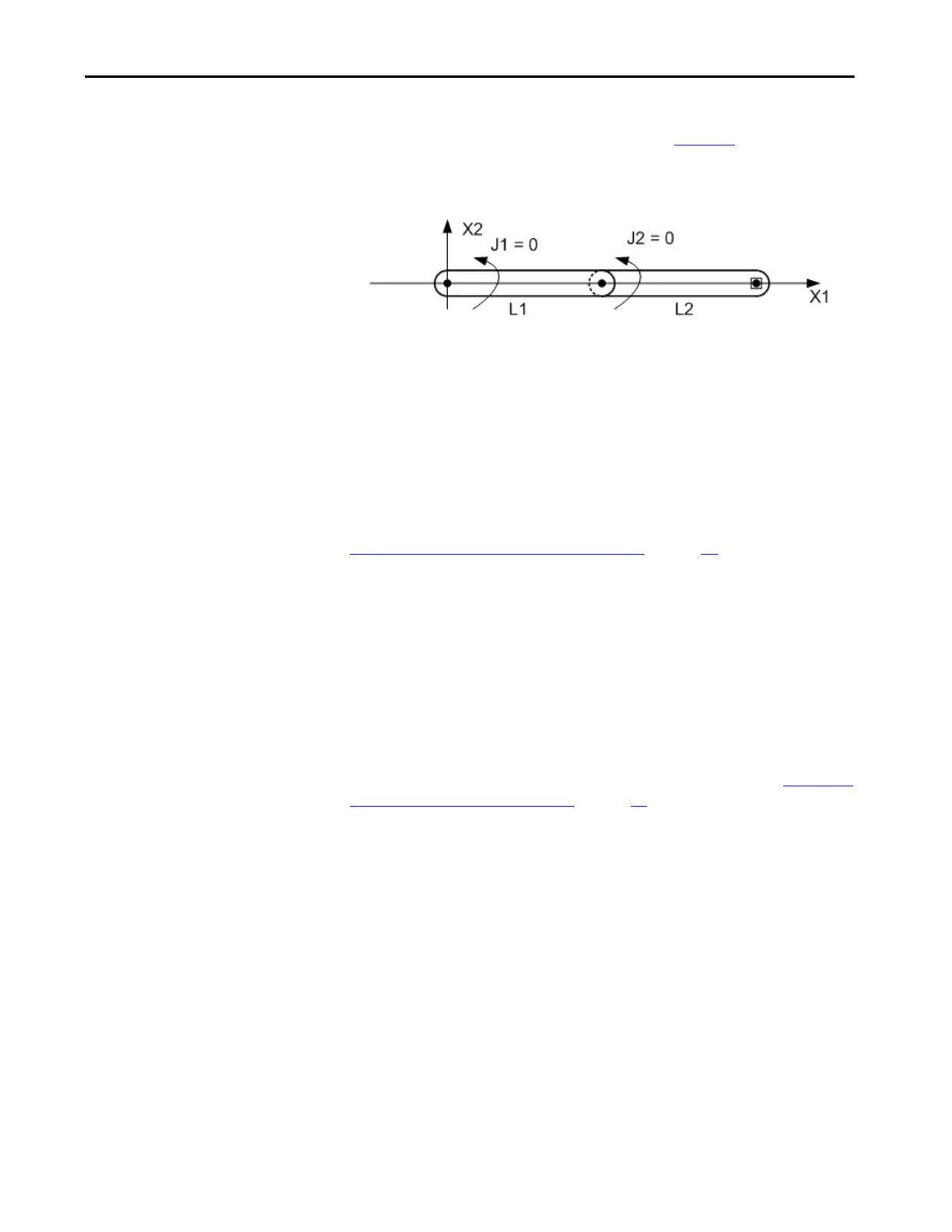
Figure 35 - Joint and Link Start Position that Kinematics Equations use for the SCARA
Independent Robots
• +J1 is measured counterclockwise around +X3 axis starting at an angle
of J1 =0.0 when L1 is along the X1 axis.
• +J2 is measured counterclockwise starting with J2 = 0 when Link L2 is
aligned with Link L1.
• +J3 is a prismatic axis that moves parallel to +X3 axis.
For information about alternate methods for establishing a reference frame, see
Configure an Articulated Independent Robot
on page 53.
When configuring the parameters for the Source coordinate system and the
Target coordinate system for a SCARA Independent robot, keep the following
information in mind:
• Set the transform dimension value to two for both the source and target
coordinate systems because only J1 and J2 are involved in the
transformations.
• The Z axis is configured as a member of both the source and target
coordinate systems.
For additional information about establishing a reference frame, see Configure
an Articulated Independent Robot on page 53.

 Loading...


