92 Rockwell Automation Publication MOTION-UM002E-EN-P - June 2016
Chapter 5 Configure an Articulated Dependent Robot
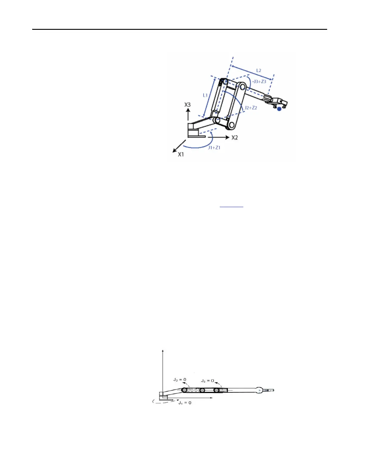
Figure 40 - Articulated Dependent 1
Before you begin establishing the Joint-to-Cartesian reference frame
relationship, it is important to know some information about how the
Kinematic mathematical equations in the ControlLogix® controllers were
written. The equations were written as if the Articulated Dependent robot
joints were positioned as shown in Figure 40
.
• +J1 is measured counterclockwise around the +X3 axis starting at an
angle of J1=0 when L1 and L2 are both in the X1-X2 plane.
• +J2 is measured counterclockwise starting with J2=0 when L1 is parallel
to X1-X2 plane.
• +J3 is measured counterclockwise with J3=0 when L2 is parallel to the
X1-X2 plane.
When your robot is physically in this position, the Logix Designer application
Actual Position tags for the axes must be:
•J1 = 0
•J2 = 0
•J3 = 0
Figure 41 - Articulated Dependent 2

 Loading...


