1–2 Planning Your Configuration
Publication
1756–6.5.15 – July 1998
The following examples illustrate a data-mapping plan for a
DeviceNet network.
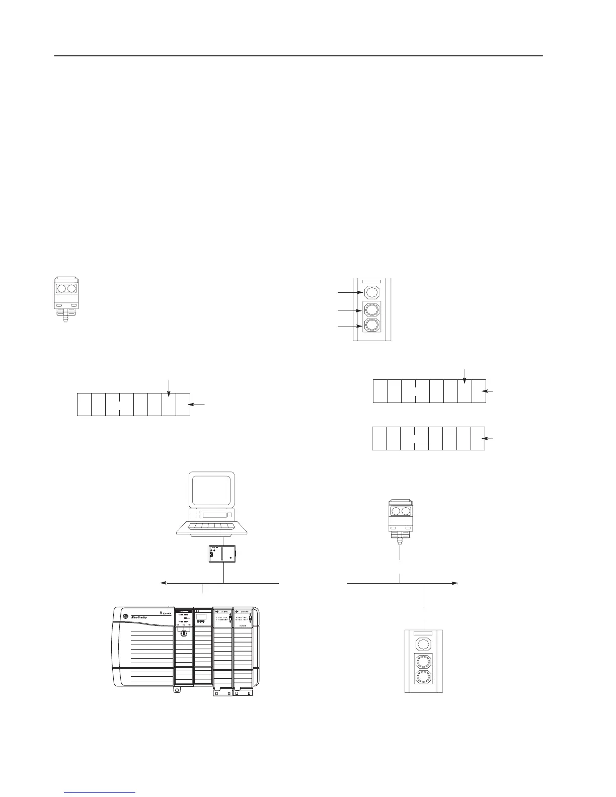
About This Example
This example has the following characteristics:
• a PC host platform
• a 1756–DNB communication module
• a Series 9000 photoelectric sensor (strobed)
• a RediSTATION operator interface (polled)
Important: In the following examples, output is data sent to a
device. Input is data collected from a device.
PC running Windows
NT or Windows 95
containing DeviceNet
Manager software
DeviceNet network
Two input bits from the photoelectric
sensor will be mapped: one status bit and
one data bit.
Two input bits from the RediSTATION
operator interface will be mapped: one bit
for the green start button and one bit for the
red stop button. One output bit for the
operator interface will also be mapped: one
bit for the operator interface’s indicator light
(on/off). Bit 4 of the input byte indicates if
the bulb is missing.
Series 9000 photoelectric sensor
RediSTATION operator interface
indicator light
green start button
red stop button
1 byte
1 byte
1 byte
input
output
The photoelectric sensor
produces one byte of input
data in response to the
strobe message.
The RediSTATION
operator interface produces
one byte of input data and
consumes one byte of
output data.
status
bit
data
bit
bit for green button
bit for
red button
bit for
indicator light
Node 1
Node 2
RediStation
operator interface
photoelectric
sensor
input
1770–KFD
communciation
module
DD
S
SD
Node 62
1756–DNB in ControlLogix chassis
DEVICENET
01234567
01234567
01234567
Node 15
P
Ex
es

 Loading...


