2–3Before You Begin
Publication
1756–6.5.15 – July 1998
Communicating with Your Devices
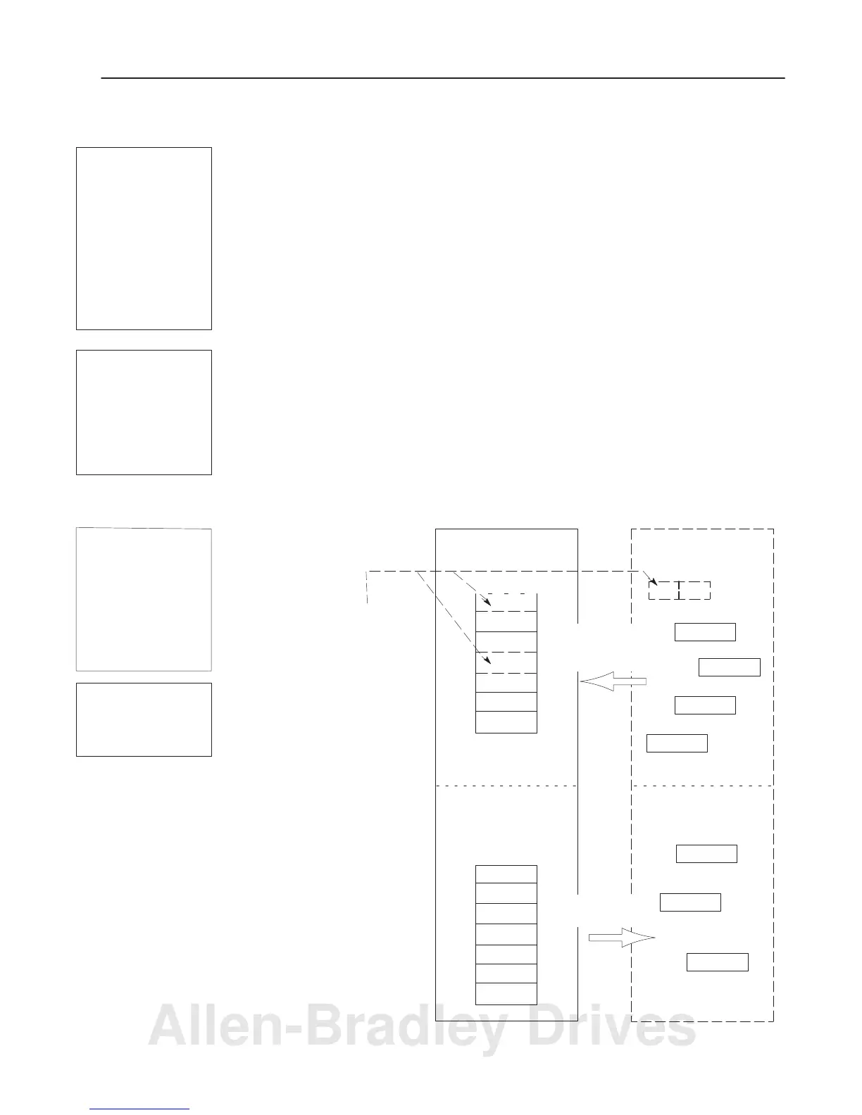
Your communication module communicates with scanned device via
strobe, poll, change of state, and cyclic messages. It uses these
messages to solicit data from or deliver data to each device. Data
received from the devices, or input data, is organized by the
communication module and made available to your host platform.
Data received from your host platform, or output data, is organized
in the communication module and sent on to your devices.
Important: Throughout this document, input and output are defined
from the host platform’s point-of-view. Output is data
sent from the host platform to a device. Input is data
collected by the host platform from a device.
Important: All data sent and received on a DeviceNet network is in
byte lengths. A device may, for example, produce only
two bits of input information. Nevertheless, since the
minimum data size on a DeviceNet network is one byte,
two bits of information are included in the byte of data
produced by the device. In this case (only two bits of
input information), the upper six bits are insignificant.
1756–DNB Communication Module DeviceNet Devices
X
Y
Z
Input Data Storage
Output Data Storage
C
D
E
B
A1
B
C
D
E
X
Y
Z
Input Data From
DeviceNet Devices
Output Data To
DeviceNet Devices
output from the
host platform
input from the
devices to the
host platform
A2
A1
A2
Bits can be mapped to separate
communication module memory
locations; this is known as map segment-
ing. This concept is illustrated in “byte A.”
Byte
0
1
2
3
4
5
...
A strobe message is a
multicast transfer of data
(which is 64 bits in length)
sent by the communica-
tion module that solicits a
response from each
strobed slave device.
There is one bit for each
of the possible 64 node
addresses. The
devices respond with
their data, which can be
as much as 8 bytes.
A poll message is a
point-to-point transfer of
data (0 to 255 bytes))
sent by the communica-
tion module that solicits a
response from a single
device. The device
responds with its input
data (0 to 255 bytes).
A change of state
message is a point-to-
point transfer of data sent
whenever a data
change occurs or at a
user-configurable
heartbeat rate. This does
not solicit response data,
but may receive an
acknowledge message.
A cyclic message is
sent only at a
user-configurable rate.
Allen-Bradley Drives

 Loading...


