1–4 Planning Your Configuration
Publication
1756–6.5.15 – July 1998
Part II – RediSTATION Operator Interface
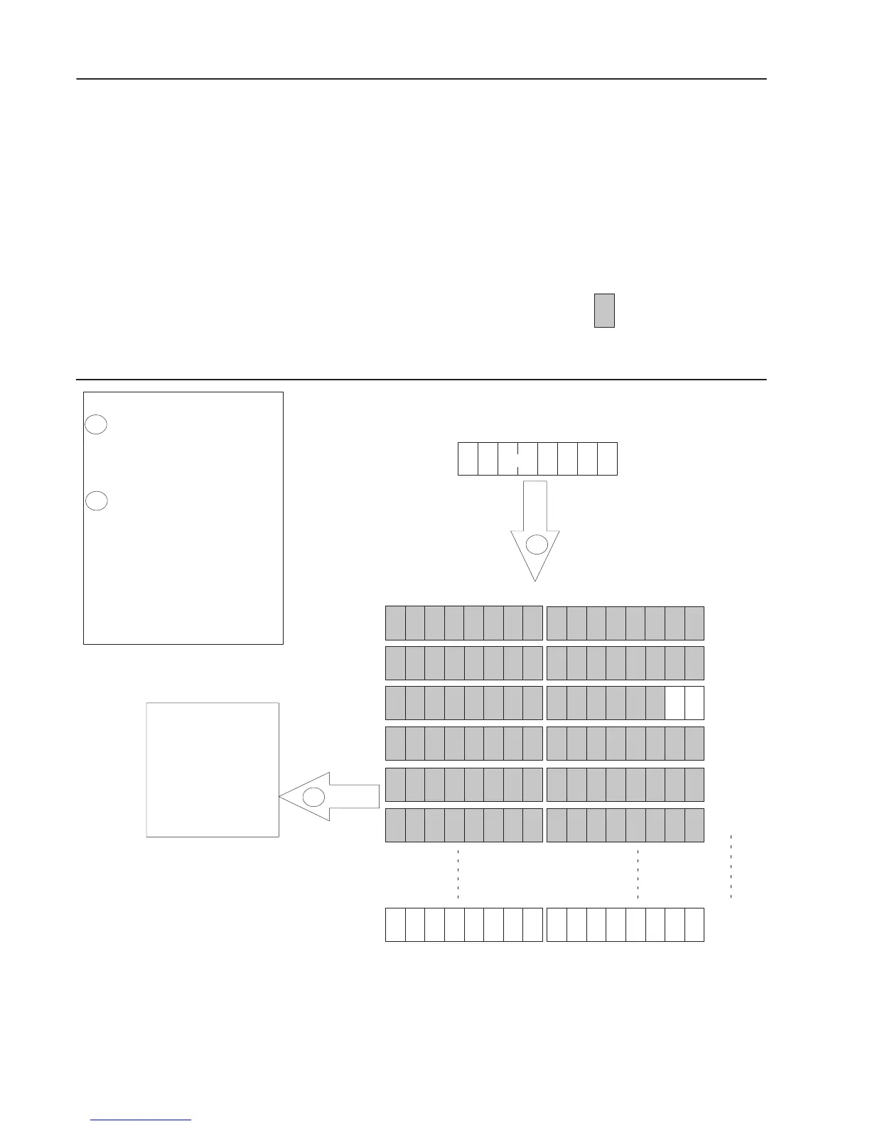
Mapping Input Data
The RediSTATION operator interface’s input byte is mapped to the
communication module’s data table. In the RediSTATION’s byte is a
bit for the:
• red button (on/off)
• green button (on/off)
0000 0000 0000 0000
0000 0000 0000
00
00
0000 0000 0000 0000
0000 0000 0000 0000
0000 0000 0000 0000
0000 0000 0000 0000
Word 0
Word 1
Word 2
Word 3
Word 4
Word 5
Host Platform
Input Data File
R = bit for red button
G = bit for green button
usage example: 2R = red-button bit for station #2
2G = green-button bit for station #2
word 2
word 1
RediSTATION Input Bytes
start/stop station node address 2
2R2G
1 byte
The bits for the
RediSTATION operator
interface’s red and green
buttons are mapped into the
communication module’s data table.
1
2
What’s Happening?
= unused bits
e
ST
T
O
s
word 3
word 4
word 5
1756–DNB Communication Module Input Image Table
Address
Data
up to
word
123
Example: The green start button from
RediSTATION #2 (2G) appears in the host
platform’s input image-file word 2, bit 1.
1
2 The data table is then
transferred to the host
platform’s input data file.
Important: The communication
module only makes the data
available for the host platform to
read. The communication
module does not move the data
to the host platform.
word 0
1S 1D
2G 2R

 Loading...


