B–6 Scan List Example
Publication
1756–6.5.15 – July 1998
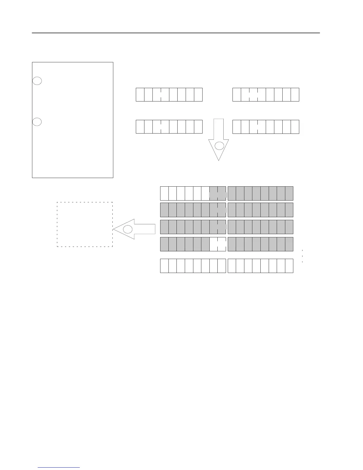
RediSTATION Operator Interface Input Mapping Scheme Example
RediSTATION Operator Interface Input Bytes
start/stop station node address 5 start/stop station node address 6
start/stop station node address 7 start/stop station node address 8
5R5G
7R7G
6R6G
8R8G
1 byte
1 byte
1 byte
1 byte
1
The input image table is then
transferred host platform.
Important: The communication
module only makes the data
available for the processor to
read. The communication
module
does not move the data to
the processor.
What’s Happening?
1756–DNB Communication Module Input Image Table
1
2
The bits for each
RediSTATION operator
interface’s red and green
buttons are mapped into the
communication module’s input
image table.
0000 0000 0000 0000
0000 0000 0000 0000
0000 0000 0000 0000
0000 0000 0000 0000
0000 0000 0000 0000
0000 0000 0000 0000
Word 0
Word 1
Word 2
Word 3
Word 4
Word 5
Host Platform
Input Data File
5G
7G
5R
6R
7R
word 1
2
word 2
word 3
word 4
6G
8R8G
word 1023

 Loading...


