370 Rockwell Automation Publication 2198-UM002G-EN-P - February 2019
Appendix A Interconnect Diagrams
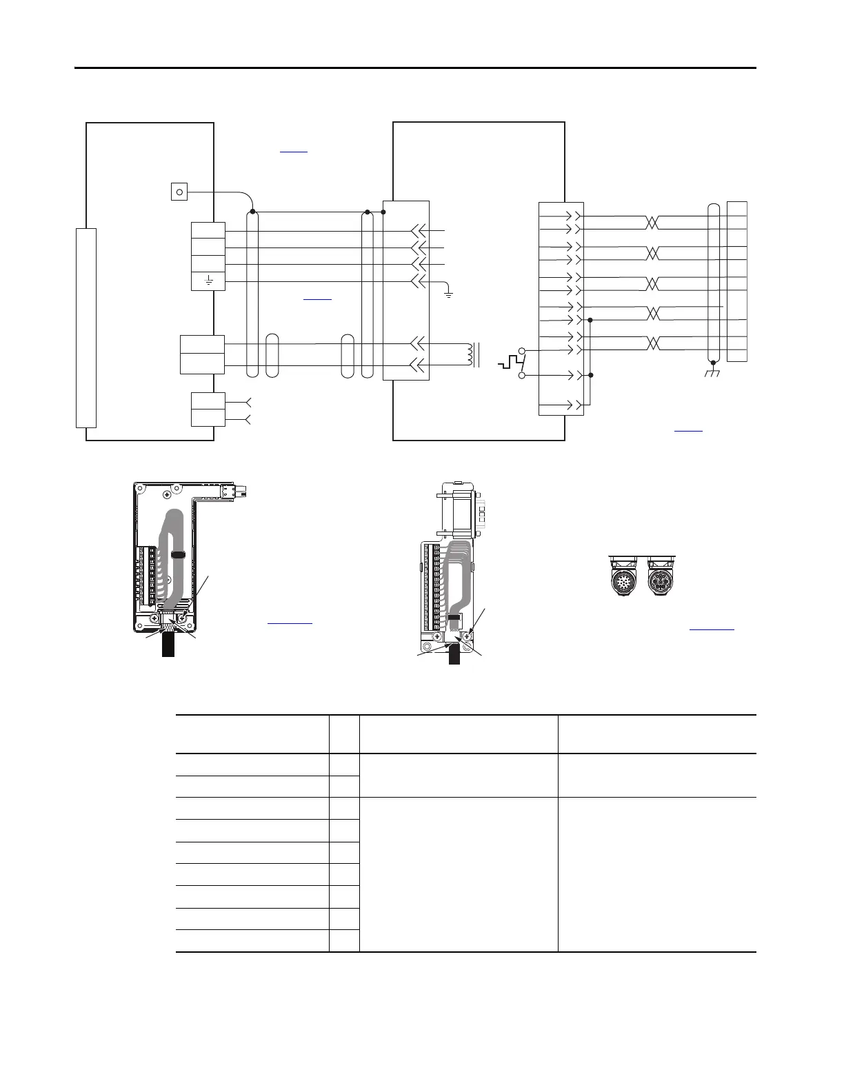
Figure 196 - Kinetix 5700 Drives with MP-Series Electric Cylinders
Table 171 - MP-Series Electric Cylinder Power and Feedback Cables
C
B
A
MBRK+
MBRK-
F
G
U
V
W
SIN+
SIN-
COS+
COS-
DATA+
DATA-
–
ECOM
GREEN
WHT/GREEN
GRAY
WHT/GRAY
BLACK
WHT/BLACK
RED
WHT/RED
3
4
5
6
1
2
9
10
1
2
3
4
5
10
6
14
12
+9VDC
TS
ORANGE
WHT/ORANGE
11
13
7
11
GND
D
U
V
W
1
2
D+
D-
1
2
4
3
2
1
MBRK +
MBRK -
Brown
Black
Blue
Green/Yellow
White
Black
Shield
14
11
10
7
6
5
4
3
2
1
1
2
3
4
5
6
7
8
9
10
11
12
13
14
15
1
2
34
5
6
7
8
910111213141516
COM
Motor Brake
Motor Brake
(BC) Connector
Motor Power
(MP) Connector
MPAR-Bxxxxx and MPAI-Bxxxxx
Electric Cylinders with
High Resolution Feedback
Motor Feedback
(MF) Connector
Three-phase
Motor Power
Motor
Feedback
Thermostat
Grounding Techniques for Feedback Cable Shield
Cable Clamp
Exposed shield secured
under clamp.
Clamp Screws (2)
Refer to table on page 341
for note information.
Cable Shield
Clamp
Note 7
Refer to Hiperface to DSL Feedback
Converter Kit Installation Instructions,
publication 2198-IN006, for converter kit
specifications.
Refer to Ta bl e 171 for
(flying-lead) motor feedback cable.
Note 19
Refer to Ta bl e 171 for
motor power cable.
Notes 19
Power Connector
Feedback Connector
SpeedTec DIN
Motor Connectors
Refer to feedback kit
illustrations (lower left)
for proper grounding technique.
2198-H2DCK
Hiperface-to-DSL
Feedback Converter Kit
2198-Dxxx -ERSx
Kinetix 5700 Servo Drives
2198-H2DCK Feedback
Converter Kit or
2198-K57CK-D15M Feedback
Connector Kit
Universal Feedback
(UFB) Connector
Cable ClampExposed shield secured
under clamp.
Clamp Screws (2)
Refer to Universal Feedback Connector Kit
Installation Instructions, publication 2198-IN010
,
for connector kit specifications.
2198-K57CK-D15M
Universal Feedback
Connector Kit
Note 8
MP-Series™ Electric Cylinder
Cat. No.
Frame
Power Cable
Cat. No.
Feedback Cable
Cat. No.
MPAR-B1xxx (series A and B) 32
2090-XXNPMF-16Sxx (standard) or
2090-CPxM4DF-16AFxx (continuous-flex)
2090-XXNFMF-Sxx (standard) or
2090-CFBM4DF-CDAFxx (continuous-flex)
MPAR-B2xxx (series A and B) 40
MPAR-B1xxx (series B and C) 32
2090-CPxM7DF-16AAxx (standard) or
2090-CPxM7DF-16AFxx (continuous-flex)
2090-CFBM7DF-CEAAxx (standard) or
2090-CFBM7DF-CEAFxx (continuous-flex)
MPAR-B2xxx (series B and C) 40
MPAR-B3xxx 63
MPAI-B2xxxx 64
MPAI-B3xxxx 83
MPAI-B4xxxx 110
MPAI-B5xxxx 144
 Loading...


