272 Rockwell Automation Publication 1756-RM006K-EN-P - November 2018
Input
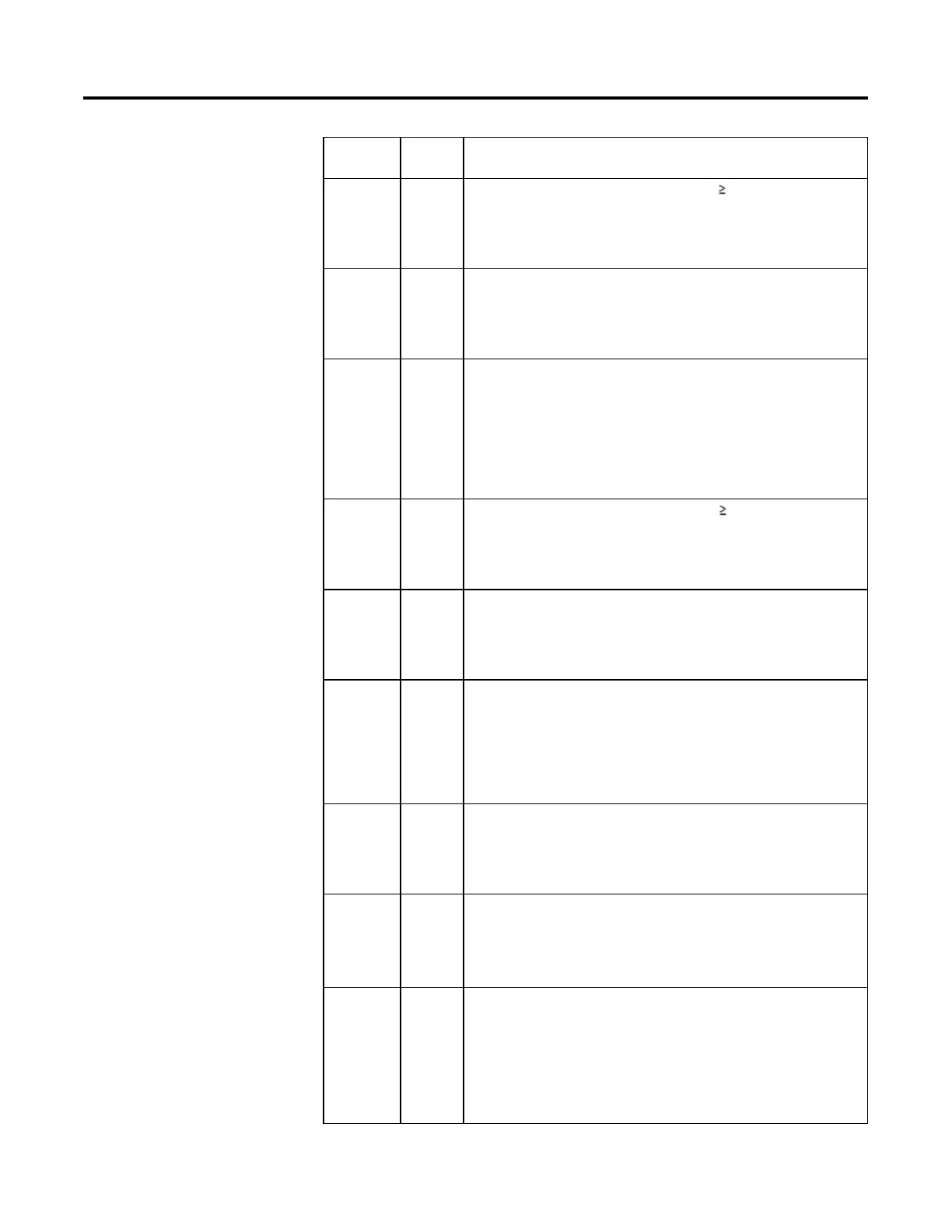
Parameter
Data Type Description
ShapeKpPlus REAL The positive Kp shaping gain multiplier. Used when In is 0. If invalid, the instruction
clamps ShapeKpPlus at the limits and sets the appropriate bit in Status. Not used when
NonLinearMode is cleared.
Valid = 0.1 to 10.0
Default = 1.0
ShapeKpMinus REAL The negative Kp shaping gain multiplier. Used when In is < 0. If invalid, the instruction
clamps ShapeKpMinus at the limits and sets the appropriate bit in Status. Not used when
NonLinearMode is cleared.
Valid = 0.1 to 10.0
Default = 1.0
KpInRange REAL The proportional gain shaping range. Defines the range of In (error) over which the
proportional gain increases or decreases as a function of the ratio of | In | / KpInRange.
When | In | > KpInRange, the instruction calculates the change in proportional error using
entered the Kp shaping gain x (In - KpInRange). If invalid, the instruction clamps KpInRange
at the limits and sets the appropriate bit in Status. Not used when NonLinearMode is
cleared.
Valid = any float > 0.0
Default = maximum positive float
ShapeWldPlus REAL The positive Wld shaping gain multiplier. Used when In is 0. If invalid, the instruction
clamps ShapeWldPlus at the limits and sets the appropriate bit in Status. Not used when
NonLinearMode is cleared.
Valid = 0.0 to 10.0
Default = 1.0
ShapeWldMinu
s
REAL The negative Wld shaping gain multiplier. Used when In is < 0. If invalid, the instruction
clamps ShapeWldMinus at the limits and sets the appropriate bit in Status. Not used when
NonLinearMode is cleared.
Valid = 0.0 to 10.0
Default = 1.0
WldInRange REAL The integral gain shaping range. Defines the range of In (error) over which integral gain
increases or decreases as a function of the ratio of | In | / WldInRange. When
|In| > WldInRange, the instruction limits In to WldInRange when calculating integral error.
If invalid, the instruction clamps WldInRange at the limits and sets the appropriate bit in
Status. Not used when NonLinearMode is cleared.
Valid = any float > 0.0
Default = maximum positive float
NonLinearMod
e
BOOL Enable the non-linear gain mode. When set, the instruction uses the non-linear gain mode
selected by ParabolicLinear to compute the actual proportional and integral gains. When
cleared, the instruction disables the non-linear gain mode and uses the Kp and Wld values
as the proportional and integral gains.
Default is cleared.
ParabolicLinear BOOL Selects the non-linear gain mode. The modes are linear or parabolic. When set, the
instruction uses the parabolic gain method of y=a * x
2
+ b to calculate the actual
proportional and integral gains. If cleared, the instruction uses the linear gain method of
y=a * x + b.
Default is cleared.
TimingMode DINT Selects timing execution mode.
0 = Periodic mode
1 = Oversample mode
2 = Real time sampling mode
For more information about timing modes, see Function Block Attributes.
Valid = 0 to 2
Default = 0
 Loading...


