282 Rockwell Automation Publication 1756-RM006K-EN-P - November 2018
Available Languages
Ladder Diagram
This instruction is not available in ladder diagram.
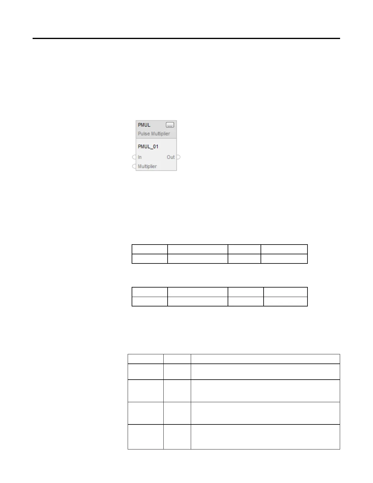
Function Block
Structured Text
PMUL(PMUL_tag);
Operands
Function Block
Operand Type Format Description
PMUL tag PULSE_MULTIPLIER Structure PMUL structure
Structured Text
Operand Type Format Description
PMUL tag PULSE_MULTIPLIER Structure PMUL structure
See Structured Text Syntax for more information on the syntax of expressions
within structured text.
PULSE_MULTIPLIER Structure
Input Parameter Data Type Description
EnableIn BOOL Enable input. If cleared, the instruction does not execute and outputs are not updated.
Default is set.
In DINT The analog input signal to the instruction.
Valid = any DINT
Default = 0
Initialize BOOL The initialize input. When set, Out is held at 0.0 and all the internal registers are set to
0. On a set to cleared transition of initialize, In
n-1
= InitialValue (not valid for Absolute
mode). When cleared, the instruction executes normally.
InitialValue DINT The initial value input. On a set to cleared transition of initialize, In
n-1
= InitialValue
Valid= any DINT
Default = 0.
 Loading...

