Select_Limit Instructions
Rockwell Automation Publication 1756-RM006K-EN-P - November 2018 363
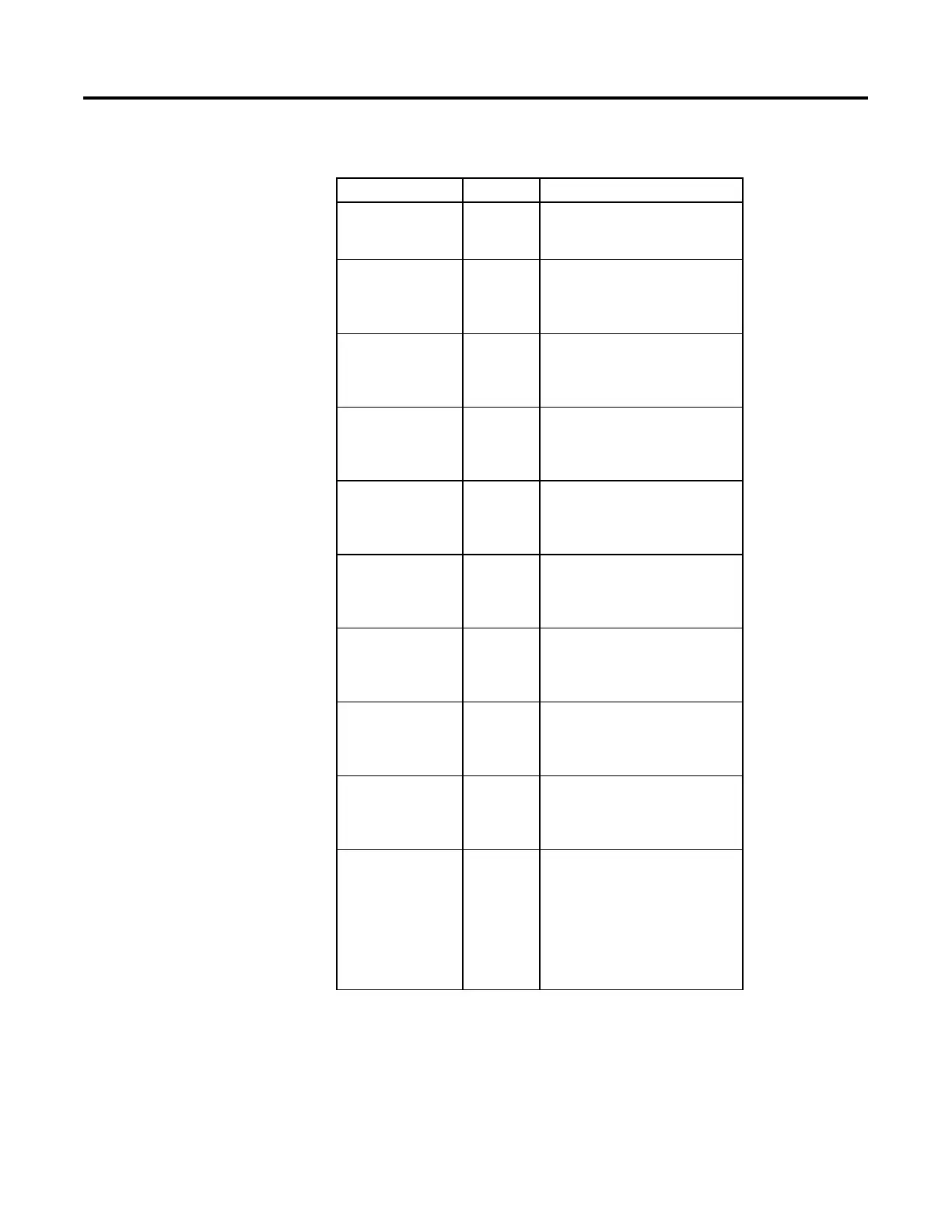
MUX Structure
Input Parameter Data Type Description
EnableIn BOOL Enable input. If cleared, the instruction does
not execute and outputs are not updated.
Default is set.
In1 REAL The first analog signal input to the
instruction.
Valid = any float
Default = 0.0
In2 REAL The second analog signal input to the
instruction.
Valid = any float
Default = 0.0
In3 REAL The third analog signal input to the
instruction.
Valid = any float
Default = 0.0
In4 REAL The fourth analog signal input to the
instruction.
Valid = any float
Default = 0.0
In5 REAL The fifth analog signal input to the
instruction.
Valid = any float
Default = 0.0
In6 REAL The sixth analog signal input to the
instruction.
Valid = any float
Default = 0.0
In7 REAL The seventh analog signal input to the
instruction.
Valid = any float
Default = 0.0
In8 REAL The eighth analog signal input to the
instruction.
Valid = any float
Default = 0.0
Selector DINT The selector input to the instruction. This
input determines which of the inputs (1-8) is
moved into Out. If this value is invalid (which
includes 0), the instruction sets the
appropriate bit in Status and holds Out at its
current value.
Valid = 1 to 8
Default = 0
 Loading...

