402 Rockwell Automation Publication 1756-RM006K-EN-P - November 2018
Available Languages
Ladder Diagram
This instruction is not available in ladder diagram logic.
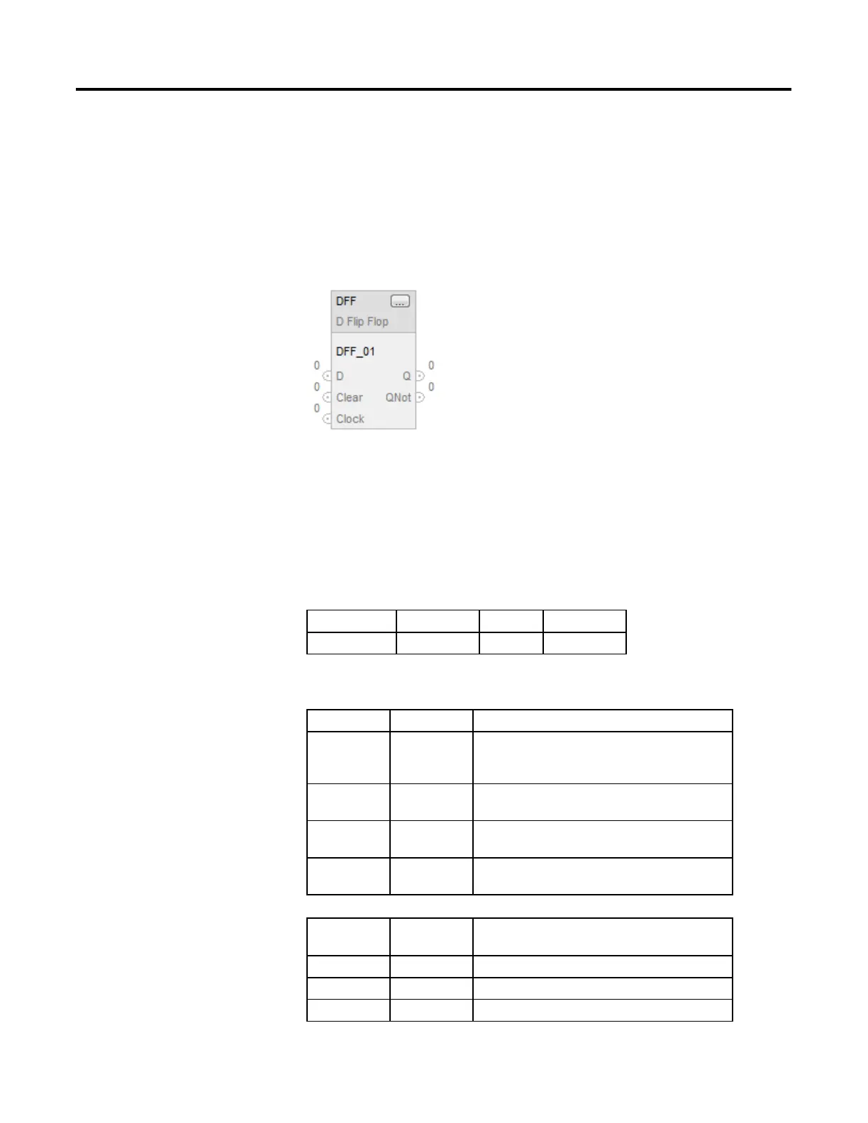
Function Block
Structured Text
DFF(DFF_tag);
Operands
Function Block
Operand Type Format Description
DFF tag FLIP_FLOP_D structure DFF structure
FLIP_FLOP_D Structure
Input Parameter Data Type Description
EnableIn BOOL Enable input. If cleared, the instruction does not execute and
outputs are not updated.
Default is set.
D BOOL The input to the instruction.
Default is cleared.
Clear BOOL Clear input to the instruction. If set, the instruction clears Q and
sets QNot.
Clock BOOL Clock input to the instruction.
Default is cleared.
Output
Parameter
Data Type Description
EnableOut BOOL Indicates if instruction is enabled.
Q BOOL The output of the instruction.
QNot BOOL The complement of the Q output.
 Loading...

