Function Block Attributes
496 Rockwell Automation Publication 1756-RM006K-EN-P - November 2018
The blocks within a specific group execute in the appropriate order in relation to
the blocks in that group.
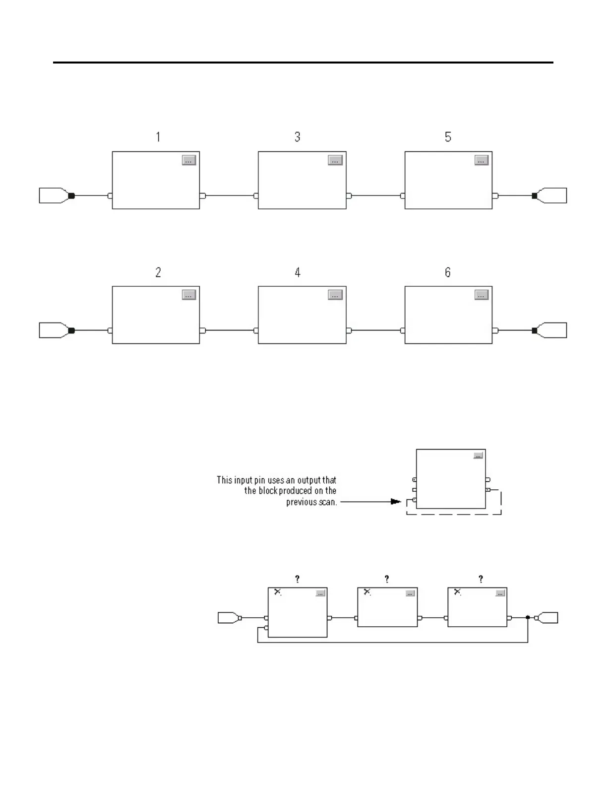
Resolve a Loop
To create a feedback loop around a block, wire an output pin of the block to an
input pin of the same block. The following example is OK. The loop contains only
a single block, so execution order does not matter.
If a group of blocks are in a loop, the controller cannot determine which block to
execute first. In other words, it cannot resolve the loop.
To identify which block to execute first, mark the input wire that creates the loop
(the feedback wire) with the Assume Data Available indicator. In the following
 Loading...


