EasyManuals Logo
Home>Allen-Bradley>Controller>LOGIX 5000

Allen-Bradley LOGIX 5000 User Manual

Allen-Bradley LOGIX 5000
561 pages
To Next Page IconTo Next Page
To Previous Page IconTo Previous Page
Page #498 background imageLoading...
Page #498 background image
Chapter 9
Function Block Attributes
498 Rockwell Automation Publication 1756-RM006K-EN-P - November 2018
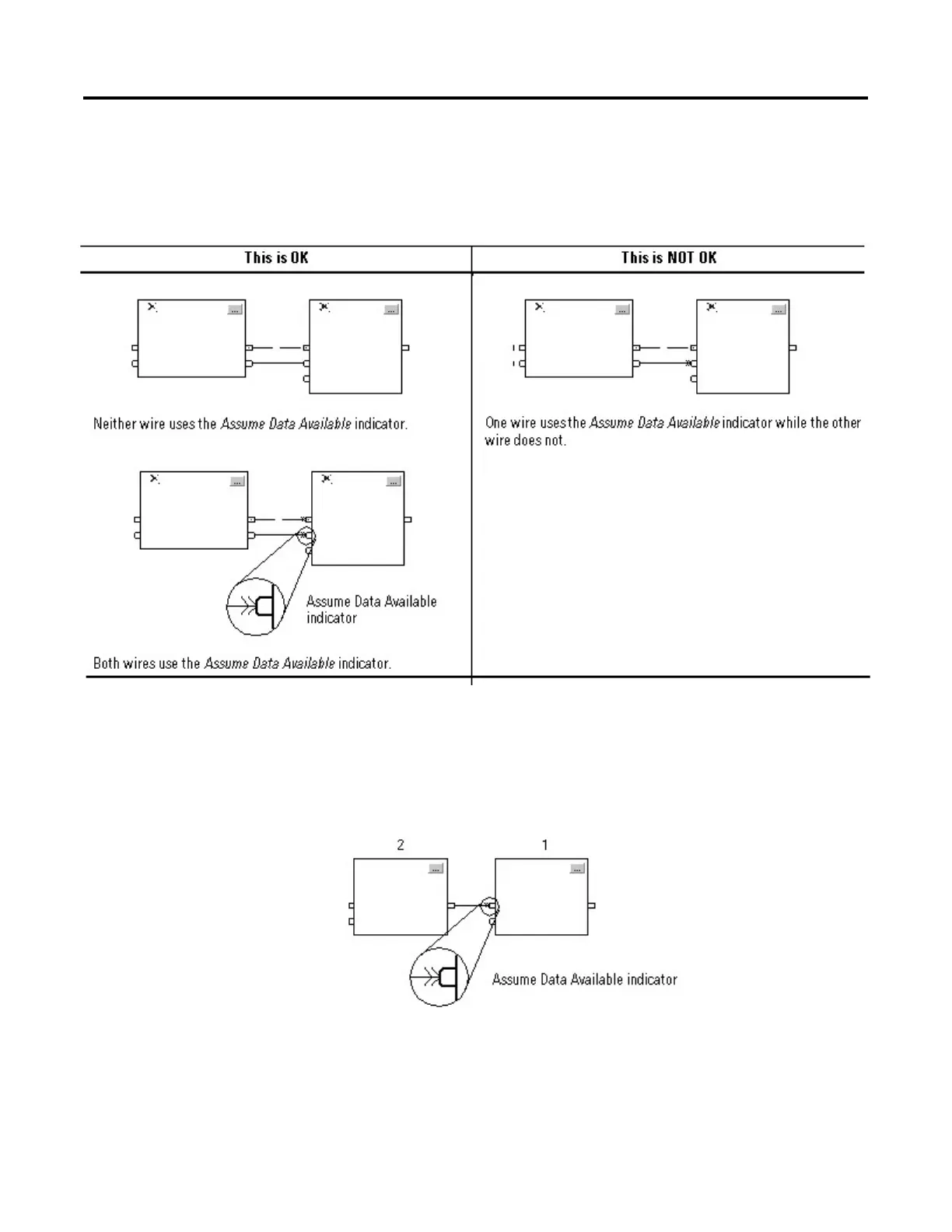
Resolve Data Flow Between Two Blocks
If you use two or more wires to connect two blocks, use the same data flow
indicators for all of the wires between the two blocks.
Create a One Scan Delay
To produce a one scan delay between blocks, use the Assume Data Available
indicator. In the following example, block 1 executes first. It uses the output from
block 2 that was produced in the previous scan of the routine.
Summary
In summary, a function block routine executes in this order:
1. The controller latches all data values in IREFs.

Table of Contents

Other manuals for Allen-Bradley LOGIX 5000

Questions and Answers:

Question and Answer IconNeed help?

Do you have a question about the Allen-Bradley LOGIX 5000 and is the answer not in the manual?

Allen-Bradley LOGIX 5000 Specifications

General IconGeneral
BrandAllen-Bradley
ModelLOGIX 5000
CategoryController
LanguageEnglish

Related product manuals