Programming and Parameters 3-53
Enhanced Program Group (continued)
E209 [Half Bus Enable]
Enables/disables the power ride through function which allows the drive to maintain power to the
motor at 50% drive input voltage during short-term power sag conditions.
Options 0 “Disabled” (Default)
1 “Enabled”
ATTENTION: To guard against drive damage, a minimum line
impedance must be provided to limit inrush current when the power line
recovers. The input impedance should be equal or greater than the
equivalent of a 5% transformer with a VA rating 6 times the drive’s input VA
rating.
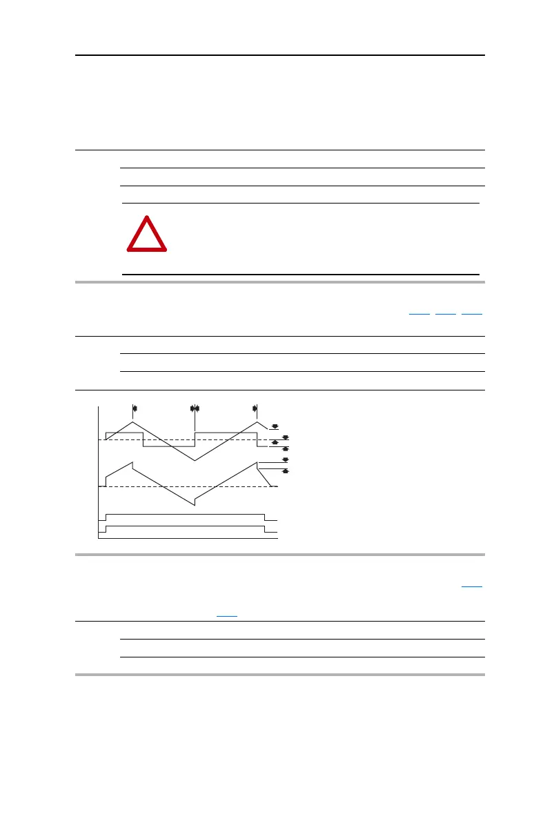
E210 [Max Traverse] Related Parameter(s): E211, E212, E213
Sets the amplitude of triangle wave speed modulation.
Values Default: 0.00 Hz (Disabled)
Min/Max: 0.00/300.0 Hz
Display: 0.01 Hz
Hertz
Seconds
Traverse Bit
212 [Traverse Dec] 211 [Traverse Inc]
Traverse Enable Bit
d302 [Fiber Status]
b001 [Output Freq]
E213 [P Jump]
E210 [Max Traverse]
E213 [P Jump]
E211 [Traverse Inc] Related Parameter(s): E210
Sets time required for the Traverse function to accelerate from the minimum to the maximum traverse
frequency. Refer to the diagram at E210
[Max Traverse].
Values Default: 0.00 Secs
Min/Max: 0.00/30.00 Secs
Display: 0.01 Secs
 Loading...


