168 Rockwell Automation Publication MOTION-UM003K-EN-P - January 2019
Chapter 8 Configuration Examples for a Kinetix Drive
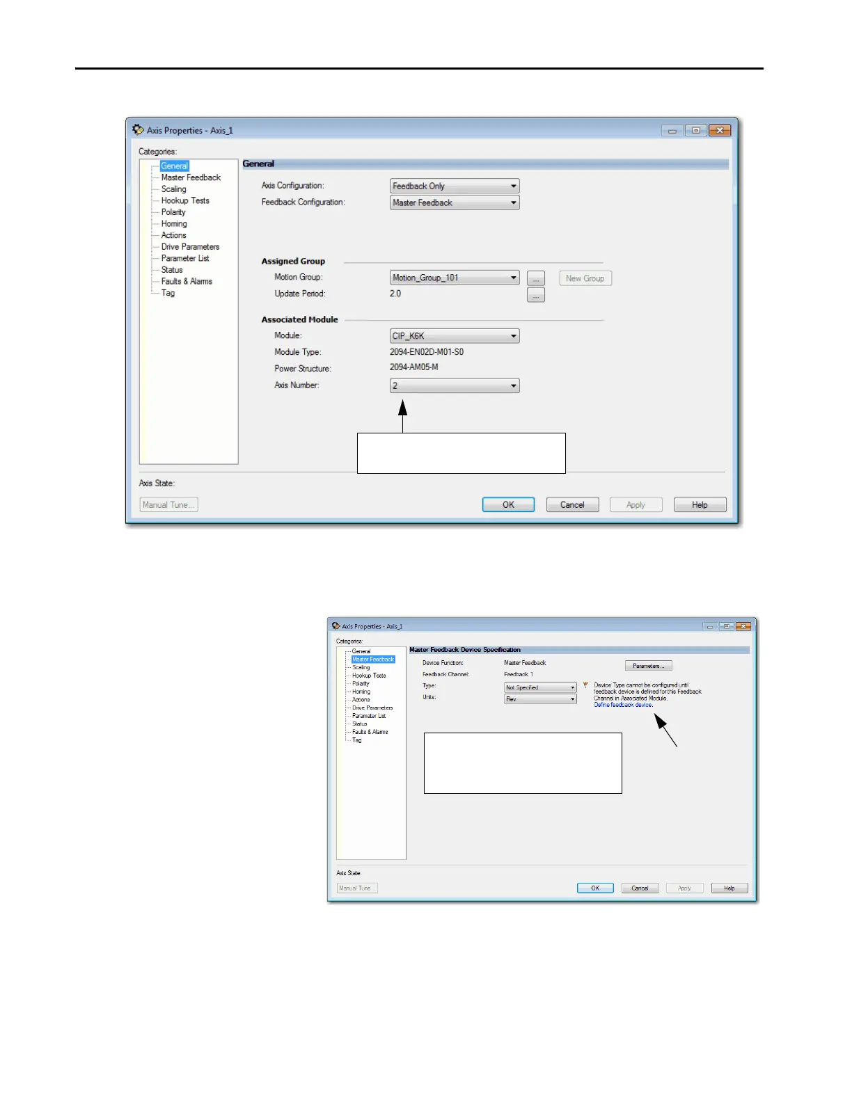
Figure 34 - Example 3: Feedback Only with Master Feedback, General Dialog Box
4. To associate the drive with the axis, click the Define feedback device
hyperlink.
Figure 35 - Example 3: Feedback Only with Master Feedback, Master Feedback Dialog Box
The Axis Number is set to 2, because Axis 1 is
already assigned to the primary axis of the drive.
Feedback 1 is the logical port for this axis that is
assigned to physical Port 2, or Aux Feedback
port of the Kinetix 6500 drive.

 Loading...


