308 Rockwell Automation Publication MOTION-UM003K-EN-P - January 2019
Appendix B Out of Box Configuration for PowerFlex Drives
Velocity Profile Effects
Table 68 summarizes the differences between profiles.
Jerk Rate Calculation
If the instruction uses or changes an S-curve profile, the controller calculates
acceleration, deceleration, and jerk when you start the instruction.
The system has a Jerk priority planner. In other words, Jerk always takes
priority over acceleration and velocity. Therefore, you always get the
programmed Jerk. If a move is velocity-limited, the move does not reach the
programmed acceleration and/or velocity.
Jerk Parameters for MAJ programmed in units of % time are converted to
engineering units as follows:
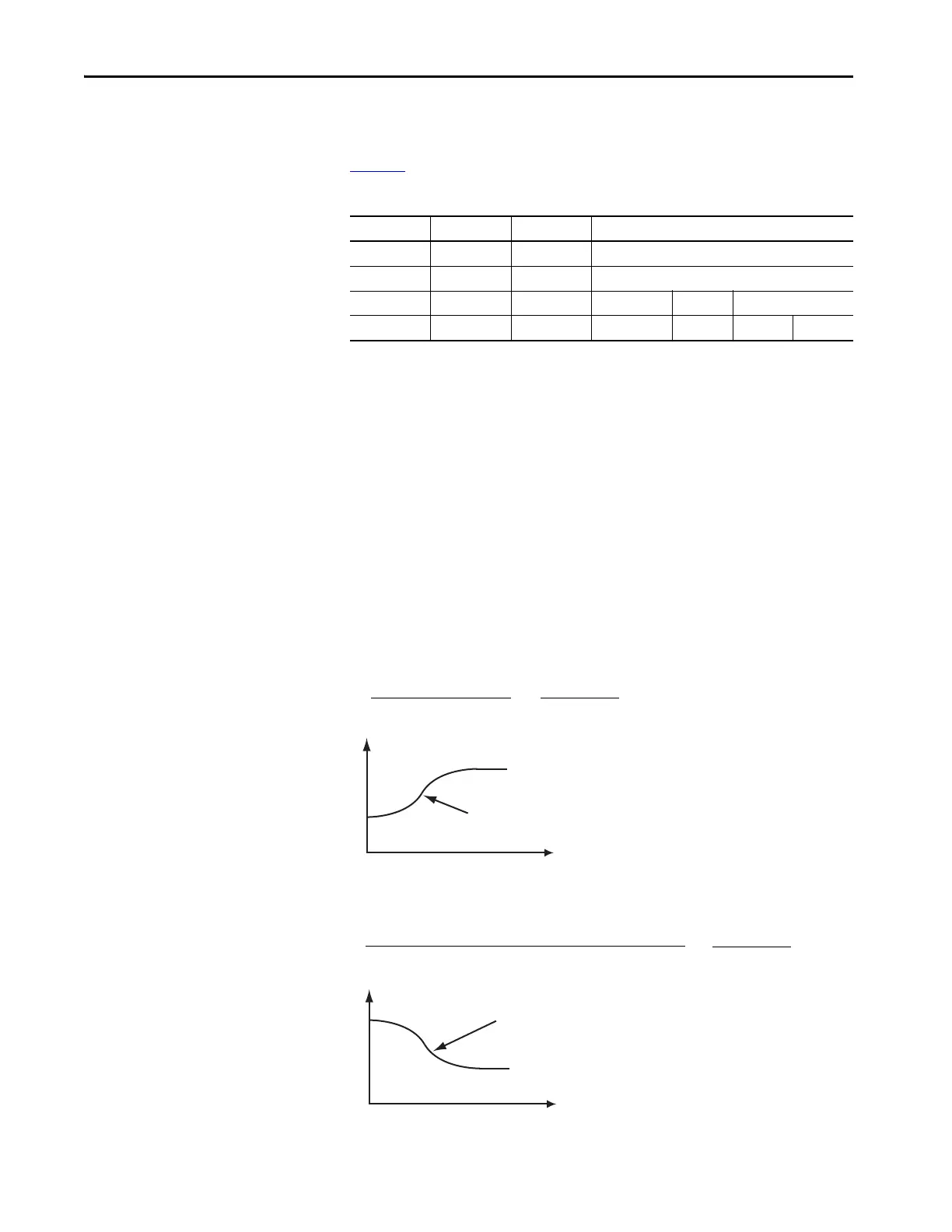
If Start Speed < MAJ Programmed Speed
If Start Velocity > MAJ Programmed Speed
Table 68 - Profile Differences
Profile ACC/DEC Motor Priority of Control
Type Time Stres s Highest to Lowest
Trapezoidal Fastest Worst Acc/Dec Velocity Position
S-curve 2X Slower Best Jerk Acc/Dec Velocity Position
Programmed Accel Rate
2
Time
Velocity
Accel Jerk
Programmed Speed
Programmed Speed
*
Accel Jerk (Units/Sec
3
) =
200
- 1
% of Time
)(
Time
Velocity
Decel Jerk
Programmed Speed
Programmed Decel Rate
2
Max (Programmed Speed, [Start Speed - Programmed Speed])
Decel Jerk (Units/Sec
3
) =
*
200
- 1
% of Time
)(

 Loading...


