206 Rockwell Automation Publication MOTION-UM003K-EN-P - January 2019
Chapter 9 Axis Configuration Examples for the PowerFlex 755 Drive
Example 6: Torque Loop with
Feedback
In this example, you are configuring the axis for Torque Loop with feedback.
1. Once you have created the AXIS_CIP_DRIVE axis, open the Axis
Properties.
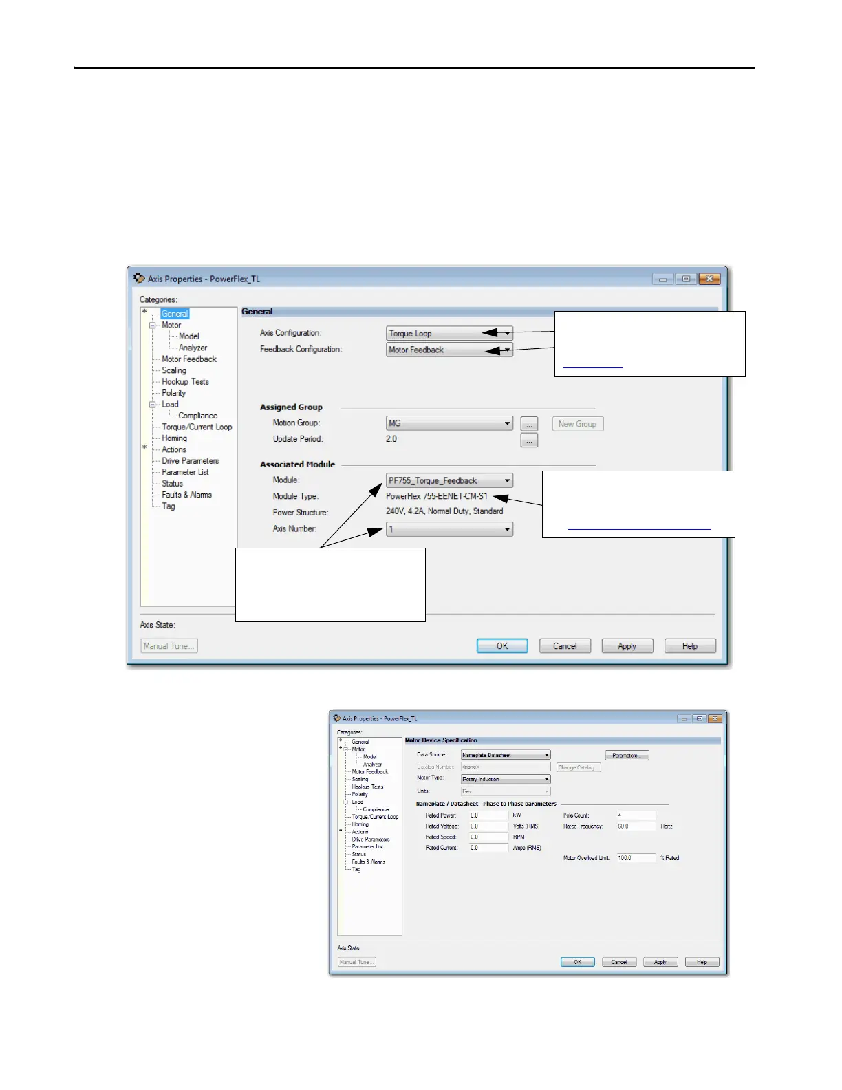
2. From the Axis Configuration pull-down menu, choose Torque Loop.
3. From the Feedback Configuration pull-down menu, choose Motor
Feedback.
Figure 81 - Example 6: Torque Loop with Motor Feedback, General Dialog Box
Figure 82 - Example 6: Torque Loop with Motor Feedback, Motor Dialog Box
Displays the type of drive you selected and
power structure you assigned via the
PowerFlex 755 drive Module Properties.
See Add a PowerFlex 755 Drive on page 99
.
The newly created PowerFlex 755 drive module
name is the default. The Axis Number defaults to
1, indicating the primary axis of the drive. Axis
Number 2 is used only for configuring a
Feedback Only axis.
Defines the controller Control Mode.
See the Integrated Motion on the EtherNet/IP
Network Reference Manual, publication,
MOTION-RM003
.

 Loading...


