Rockwell Automation Publication MOTION-UM003K-EN-P - January 2019 41
Configure Integrated Motion Control Using Kinetix Drives Chapter 3
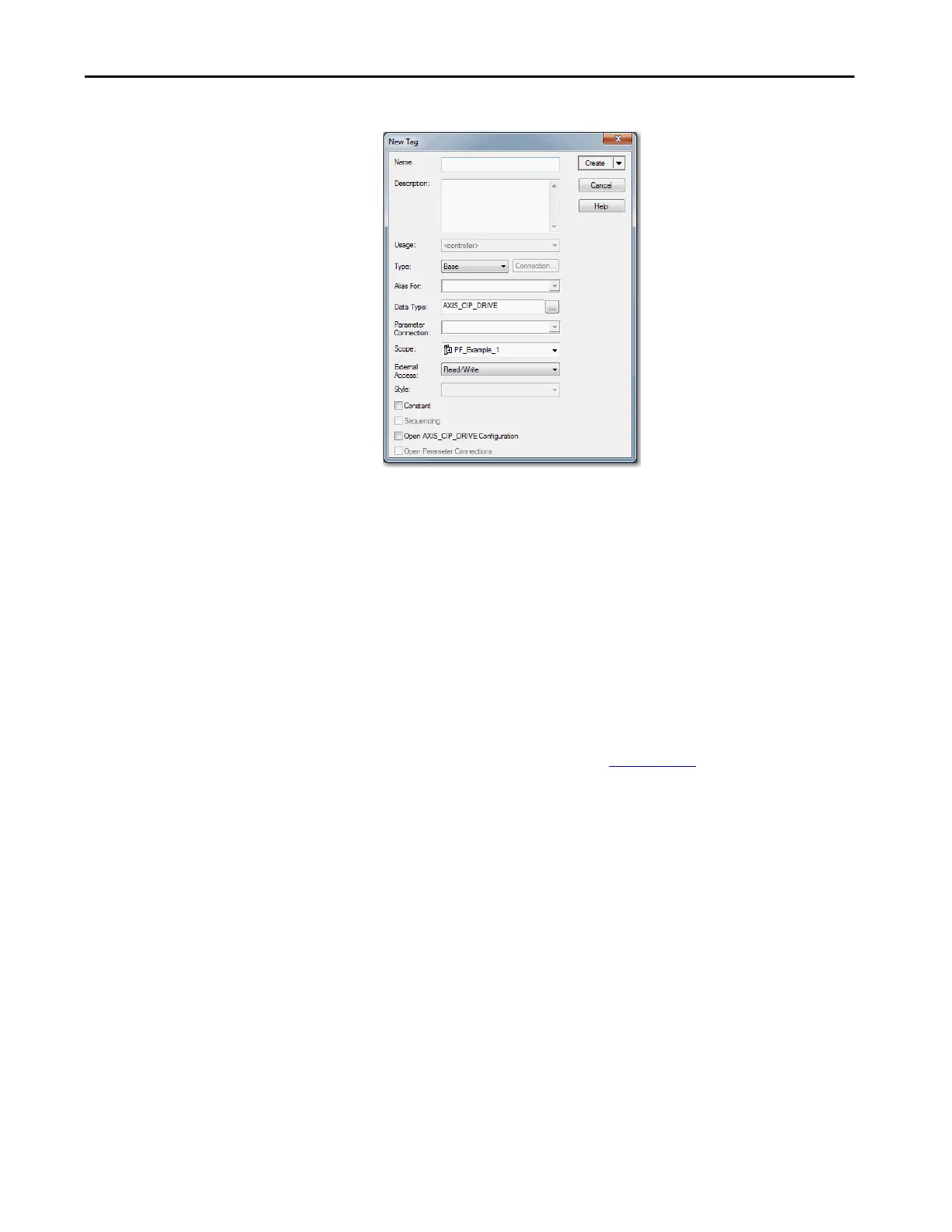
The New Tag dialog box appears.
Notice that the fields in the next steps are automatically entered for the
AXIS_CIP_DRIVE data type.
4. Type a Tag name.
5. Type a Description, if desired.
6. Choose the Tag Type.
7. Choose the Data Type AXIS_CIP_DRIVE.
8. Choose the Scope.
9. Choose the External Access.
For more information about External Data Access Control and
Constants, see the Logix5000 Controllers I/O and Tag Data
Programming Guide, publication 1756-PM004
.
10. Click Create.
Establish Feedback Port Assignments
Kinetix 350 and Kinetix 5500 drives have one Motor Feedback Port, which is
automatically assigned.
The Kinetix 6500 drive has two feedback ports. Port 1 is reserved for Motor
Feedback on the primary axis (Axis_1). Port 2 can be used either as Load
Feedback for the primary axis or as a Master Feedback for a secondary feedback
only axis (Axis_2).
To establish feedback port assignments for Kinetix 6500 drives, follow these
steps.

 Loading...


