300 Rockwell Automation Publication MOTION-UM003K-EN-P - January 2019
Chapter 14 Status, Faults, and Alarms
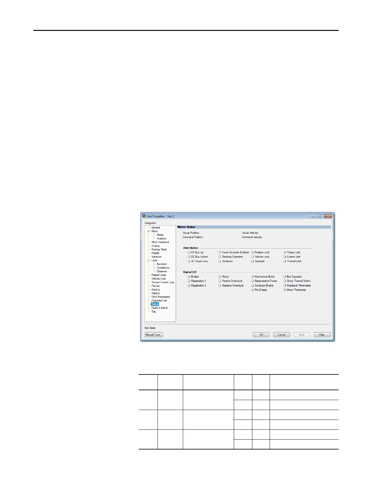
Digital I/O Status Indicators
Use the Status category to:
• Display the status of the axis
• View the current state of the axis and CIP Safety™ drive
• Manually adjust axis drive attributes
The status tab displays the following:
• Position Data (Actual and Command)
• Velocity Data (Actual and Command)
•Axis status indicators
– The indicators light up if the state has been reached. For example, if
the Torque Limit is reached, the light next to that limit turns blue.
• Digital I/O status indicators
– The indicators light up if the state has been reached. For example, if
Registration 1 is reached, the light next to Registration 1 turns blue.
You can view the status of the digital I/O indicators in the Status category of
the Axis Properties window. An example of the Status category is shown in the
following figure.
The following two tables detail the meaning of the status indicators per the axis
tags.
Bit Required/
Optional
Name Digital
I/O
Axis
Status
Description
0 R Enable Input Off 0 Enable is not active
On 1 Enable is active
1 R/E Home Input Off 0 Home is not active
On 1 Home is active
2 R/E Registration 1 Input Off 0 Reg 1 is not active
On 1 Reg 1 is active

 Loading...


