66 Rockwell Automation Publication MOTION-UM003K-EN-P - January 2019
Chapter 4 Configure Integrated Motion Control Using Kinetix 5700 Drives
6. From the pull-down menus, choose the power options appropriate for
your hardware configuration.
7. To close the New Module dialog box, click OK.
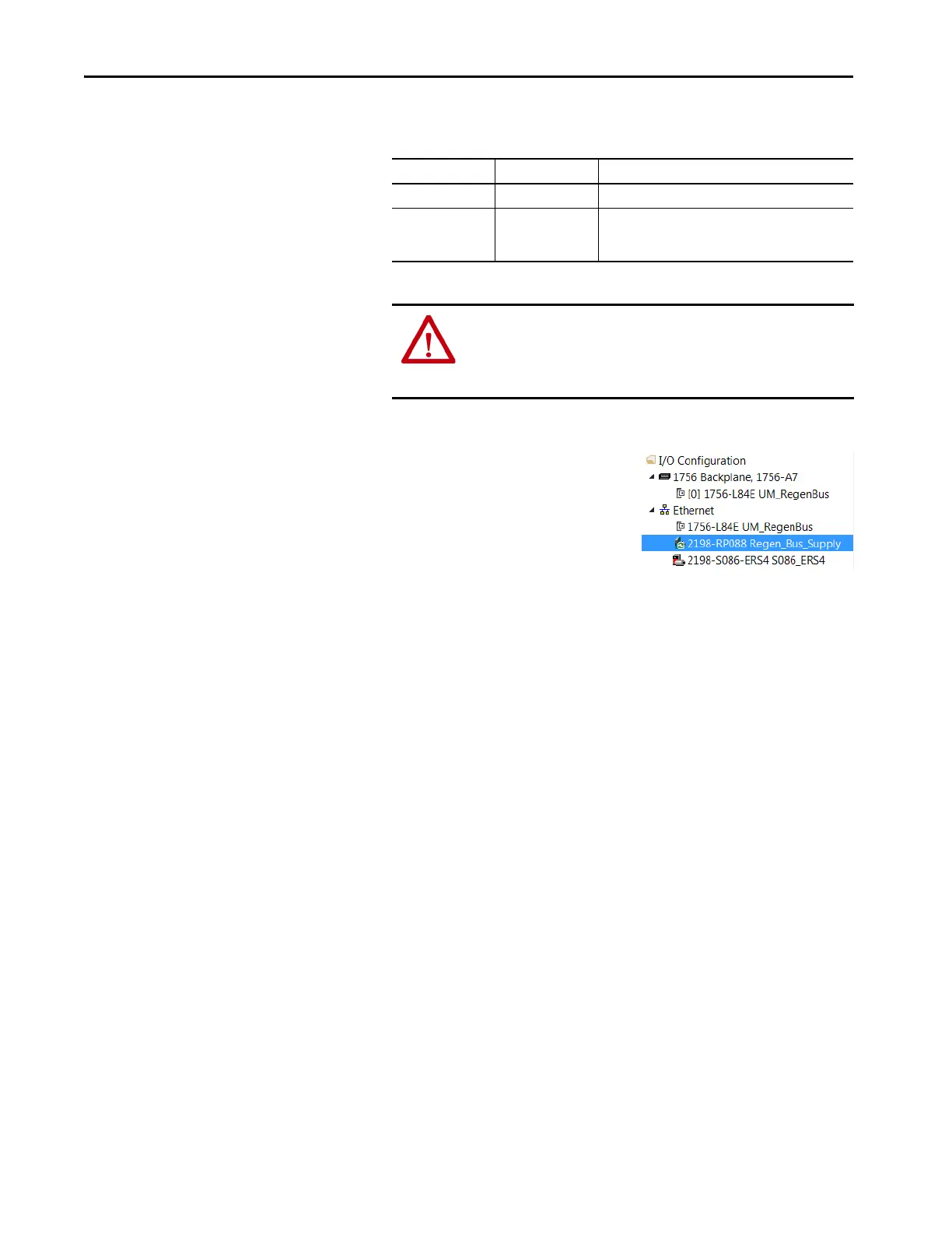
8. Your 2198-RPxxx regenerative bus
supply appears in the Controller
Organizer under the Ethernet
network in the I/O Configuration
folder.
9. Click Close to close the Select Module Type dialog box.
10. Right-click the regenerative bus supply that you created in the
Controller Organizer and choose Properties.
The Module Properties dialog box appears.
Attribute Menu Description
Bus Configuration Shared AC/DC
(1)
(1) Shared AC/DC bus configuration is the default selection for regenerative bus supplies.
Applies to 2198-RPxxx regenerative bus supply modules.
Bus-sharing Group
•Group1
•Group2
•Group3…
Applies to any bus-sharing configuration.
ATTENTION: To avoid damage to equipment all modules that are
physically connected to the same shared-bus connection system
must be part of the same Bus-sharing Group in the Logix Designer
application.
TIP To configure the remaining regenerative bus supply properties, you
must close the New Module dialog box and reopen it as the Module
Properties dialog box.

 Loading...


