82 Rockwell Automation Publication MOTION-UM003K-EN-P - January 2019
Chapter 4 Configure Integrated Motion Control Using Kinetix 5700 Drives
The axis (Axis_1 in this example) appears in the
Controller Organizer under Motion Groups>
Ungrouped Axes and is assigned as Axis 1.
6. Click Apply.
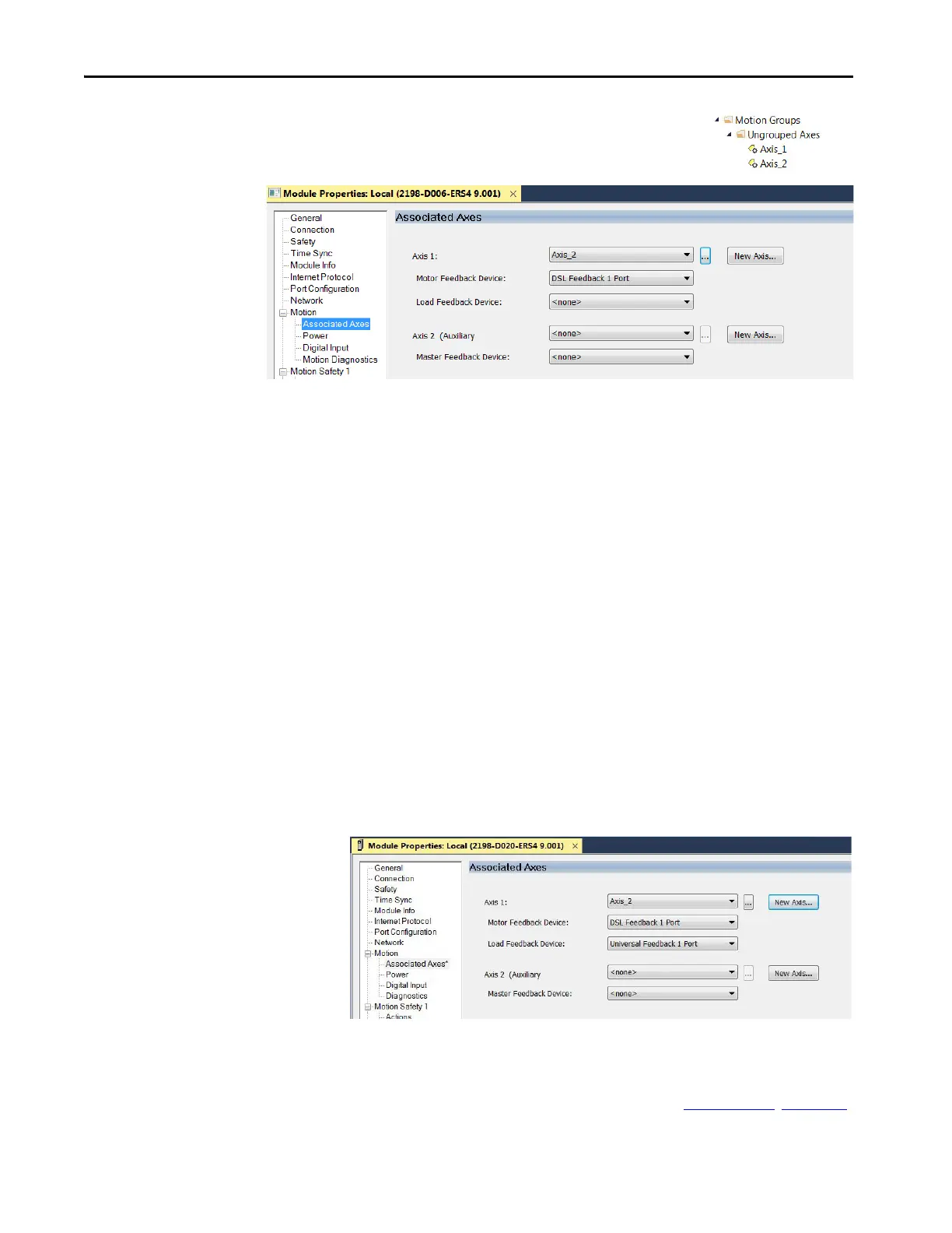
Feedback options must be defined for each axis. Each physical axis supports
motor and auxiliary feedback.
The Kinetix 5700 drive has two or four feedback ports. The single-axis
inverters support two ports and the dual-axis inverters support four ports. Port
1 is reserved for Motor Feedback on the primary axis (Axis_1). Port 2 can be
used either as Load Feedback for the primary axis or as a Master Feedback for a
secondary feedback only axis (Axis_2).
Feedback Devices are configured for either the DSL Feedback Port or the
Universal Feedback Port.
To establish Feedback Port assignments for K5700 drives, follow these steps.
1. To access the Module Properties, double-click the Kinetix 5700 drive in
the Controller Organizer.
2. Click the Associated Axes category.
3. From the Feedback Device pull-down menus, choose either a DSL
feedback port or universal feedback port to associate with your axis.
4. Click Apply.
For more information on configuration of Feedback Properties, refer to the
Kinetix 5700 servo drives User Manual, publication 2198-UM002
. Chapter 8,

 Loading...


