Rockwell Automation Publication 750-IN100B-EN-P - July 2017 131
Power Wiring Chapter 5
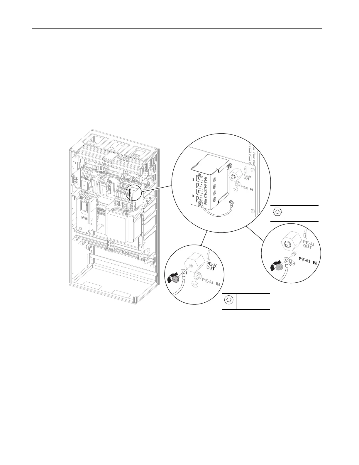
Recommended PE-A1 Jumper Configuration
The PE-A1 power jumper is connected to the TVSS module (cat. no. 20-750-
MACP-xx-TVSS). The Frame 8 and 9 AC precharge modules include an
insulated spacer and hardware for the jumper PE-A1 OUT position and
hardware for the jumper PE-A1 IN position. If a TVSS module is installed
independently from an AC precharge module, the insulated spacer (PE-A1
OUT position) and connection that is referenced to ground (PE-A1 IN
position) must be customer-supplied.
Figure 64 - Recommended PE-A1 Jumper Configuration
M6
10 mm
10.2 N•m (90 lb•in)
M6 x 10 mm
T25
5.9 N•m (52 lb•in)
Jumper PE-A1 IN
Jumper PE-A1 OUT
TVSS Module

 Loading...


