Rockwell Automation Publication 750-IN100B-EN-P - July 2017 179
I/O Wiring Chapter 6
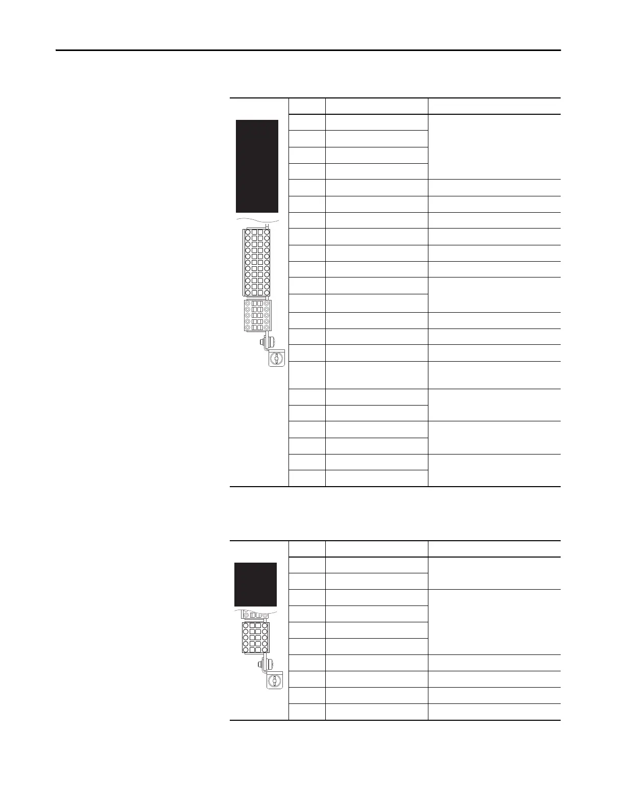
Table 65 - TB1 Terminal Designations
Terminal Name Description
-Sn Sine (–) Positive and negative terminals for Sine and
Cosine signals.
For use with 5V incremental encoders only.
+Sn Sine (+)
-Cs Cosine (–)
+Cs Cosine (+)
Is Inner Shield Heidenhain inner shield terminal
Os Outer Shield Cable shield terminal
-Xc Channel X Clock (–) Negative clock terminal (Channel X)
+Xc Channel X Clock (+) Positive clock terminal (Channel X)
-Xd Channel X Data (–) Negative data terminal (Channel X)
+Xd Channel X Data (+) Positive data terminal (Channel X)
-Hf Heidenhain Supply Feedback (–) For incremental feedback applications, tie
terminal -Hf to 5c and terminal +Hf to +5
for proper voltage regulation.
+Hf Heidenhain Supply Feedback (+)
5c Common +5V Common
+5 +5 Volt DC Power Power supply for encoder 250 mA
12c Common +12V Common
+12 +12 Volt DC Power Power supply for encoder
(10.5V @ 250 mA)
-A Encoder A (NOT) Single channel or quadrature A input or
encoder output.
(1)
(1) Inputs support 5V incremental encoders only. The encoder outputs differential voltage is 3.3V.
AEncoder A
-B Encoder B (NOT) Quadrature B input or encoder output.
(1)
BEncoder B
-Z Encoder Z (NOT) Pulse or marker input or encoder output.
(1)
ZEncoder Z
Table 66 - TB2 Terminal Designations
Terminal Name Description
-Hm Home Input (–) 12V DC @ 9 mA to 24V DC @ 40 mA
+Hm Home Input (+)
-R0 Registration Input 0 (–) Positive and negative encoder registration
terminals.
12V DC @ 9 mA to 24V DC @ 40 mA
+R0 Registration Input 0 (+)
-R1 Registration Input 1 (–)
+R1 Registration Input 1 (+)
-Yc Channel Y Clock (–) Negative clock terminal (Channel Y)
+Yc Channel Y Clock (+) Positive clock terminal (Channel Y)
-Yd Channel Y Data (–) Negative data terminal (Channel Y)
+Yd Channel Y Data (+) Positive data terminal (Channel Y)
-Sn
-Cs
IS
-Xc
-Xd
-Hf
5c
12c
-A
-B
-Z
+Sn
-Hm
+Hm

 Loading...


