3. Pull conductors through conduit and attach to circuit breaker
and ground connection. Secure service ground wire to the ma-
chine grounding screw or lug. Attach service conductors to
appropriately labeled positions on the machine terminal
block. Make sure all connections are secure.
Electrical Connections for T30 and T45
Only
All gas tumble dryers require a single service connection to TB1
of the upper unit junction box only. The serial plate reflects cur-
rent draw, breaker rating and conductor size recommendations for
the entire machine.
All electric tumble dryers require separate service connections for
each upper and lower unit. Serial Plate ratings reflect current
draw, breaker rating and conductor size recommendations per
unit.
Configuring Your Tumble Dryer for
Other Service Voltages
NOTE: Tumble dryers are not field convertible and
must be connected to service specified on serial plate.
Electrical Specifications
NOTE: Wire sizes were obtained from the Canadian
Electrical Code for 75 C. wire and are intended for use
as a guideline only. Electrical connections should be
made by a qualified electrical contractor in accordance
with all applicable local and national requirements.
NOTE: Electrical specifications below are subject to
change without notice. Always refer to product serial
plate for most current specifications of product being
installed.
CAUTION
Use copper conductors only with the following rating
when wiring appliance to electric supply: Dryer gas
and steam heat models require 187°F (75°C) mini-
mum. Dryer electric heat models require 194°F (90°C)
minimum.
W936
NOTE: Connect this appliance to an individual branch
circuit.
NOTE: 3 Phase Only – Each tumble dryer must be con-
nected to its own individual branch circuit breaker, not
fuses, to avoid the possibility of “single phasing” and
causing premature failure of the motor(s).
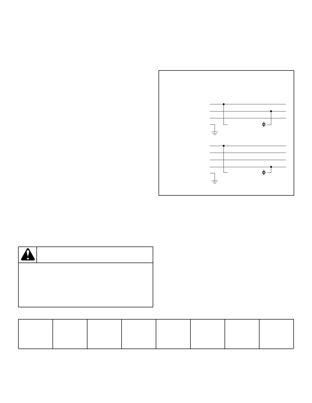
IMPORTANT: For X, D and E voltages - To obtain
200-240V from a 200-240V source, connect L1 and
L2. To obtain 220-240V from a 380-415V source, con-
nect L1 and N. Refer to Figure 22 .
220 – 240V 1
380 – 415V
200 – 240V 1
200 – 240V
N
L3
L2
L1
L3
L2
L1
TMB2471N_SVG
Figure 22
030 and 035 Series Gas Models
Voltage Code Voltage Cycle Phase Wire Full Load
Amps
Recommend-
ed Circuit
Breaker Rat-
ing Amps
Wire Size
AWG [mm
2
]
Table 19 continues...
Electrical Requirements
©
Published by permission of the copyright owner -
DO NOT COPY or TRANSMIT
68 Part No. 70686701ENR4
 Loading...