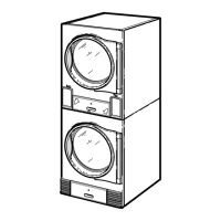
1. Auxiliary Alarm Fast-On Connection (there is a plastic
shield over the control board that must be tipped down to
access this connection)
2. Test Button
3. Light
4. Reset Button
Figure 7
To Reverse the Loading Door (030, 035
and 055 Series)
The tumble dryer is delivered with a right hinged door, but the
door can be changed to a left hinged position.
1. Disconnect power supply to tumble dryer.
2. Unlock and remove control panel. Remove two control as-
sembly mounting screws from right side. Swing open control
to access upper flange right guide lug assembly. Refer to Fig-
ure 8 .
3. Remove lint panel.
IMPORTANT: Support door and hinge assembly se-
curely to prevent it from dropping once side screws
are removed from door hinge lug.
1. Front Panel Screw
2. Front Panel
3. Control/Access Panel
4. Control Assembly Screw
5. Control Assembly
6. Lint Panel
Figure 8
4. Remove four front panel screws. Refer to Figure 8 . Keep
door hinge cams in place on door hinge lug. Pull lug and door
assembly off as one piece. Refer to Figure 9 .
5. Remove remaining front panel screws. Refer to Figure 8 .
Disconnect door switch harness from switch. Take off front
panel. Refer to Figure 9 .
6. Exchange switch and plug locations. Depress tabs with an ad-
justable pliers to remove plug and switch from front panel.
Reinstall switch, orienting button toward center of machine.
Reinstall plug in switch’s previous location. Refer to Figure
9 .
IMPORTANT: Door switch must be oriented correctly in
front panel receiving hole or tumble dryer will not oper-
ate.
Installation
©
Published by permission of the copyright owner -
DO NOT COPY or TRANSMIT
36 Part No. 70686701ENR4

 Loading...


