Setup and connection
5.2 Planning the pipes
5.2.1 Specifying supports and flange connections
NOTE
Material damage due to excessive forces and torques
exerted by the piping on the pump!
Do not exceed the p ermissible limits ( → 9.2.7 Flange
loads, Page 3 8).
1. Calculate the pipe forces, taking every possible operating
condition into account:
–Cold/warm
– Empty/full
– Unpressurized/pressurized
– Shift in position of flange s
2. Ensure the pipe supports have permanen t low-friction
properties and do not seize up due to corrosion.
5.2.2 Specifying nominal diameters
Keep the flow resistance in the pipes as low as possible.
1. Where possible, make sure the n ominal suction pipe diam-
eter is ≥ as possible to the nomina l suc tion flange diameter.
– Recommended flowratespeed<1m/s
2. Make sure the nominal pressure pipe diameter is ≥ as pos-
sible to t he nominal pressu re flange diameter.
– Recommended flowratespeed<3m/s
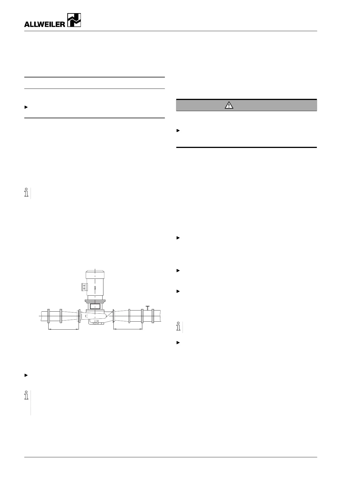
5.2.3 Specifying pipe lengths
A
B
Fig. 7 Stra ight pipe l engths upstream and downstream
of the pump (recommended)
A > 5 x nominal suction pipe diameter
B > 5 x nominal pressure pipe diameter
Maintain the recommended minimum values when
installing the pump.
Suction side: shorter pipes are possible but may restrict
the hydraulic performance.
Pressure side: shorter pipes are possible but can result in
increased operating noise.
5.2.4 Optimizing cross-section and direction changes
1. Avoid radii of curvature of less than 1.5 times the nominal
pipe diameter.
2. Avoid abrupt changes of cross-section along the piping.
5.2.5 Discharg ing leaks
WARNING
Risk of injury and poisoning due to hazardous pumped
liquids!
Safely collect any leaking pumped liquid, then discharge
and dispose of it in accordance with environmental regula-
tions.
1. Provide equipment for collecting and discharging le aking
liquids.
2. Ensure the free discharge of leaking liquids.
5.2.6 Providing safety and control devices
(recommended)
Avoid impurities
1. Integrate a filter in the suction pipe.
2. To mo nitor impurities, insta ll a differential pressure gauge
with a contact manometer.
Avoid reverse running
Install a non-return valve between the pressure flange and
the gate valve to ensure the medium does not flow back
whenthepumpisswitchedoff.
Enabling venting
Provide a vent valve on the highest pressure line position.
Avoid running empty
For suction operation: install a foot
valve in the suction pipe
to p revent th e pump and suction pip e
from running empty
during downtimes.
Make provisions for isolating and shutting off the pipes
For maintenance and repair work.
Provide shut-off devices in the suction and pressure pi pes.
Allow measurements of the operating conditions
1. Provide manometers for pressure measurements in the
suction and pressure pipes.
2. Provide load monitors (overload and underload) on the
motor side.
3. Provide for pump-side temperature measurements.
160-282/0 – 550 154 BA-2017.03 en-US NIT series 15