Layout and function
3 Layout and function
3.1 Labels
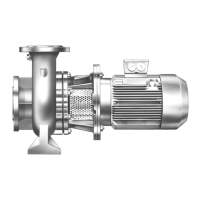
3.1.1 Type plate
11
10
13
12
4
5
6
1
2
3
98 7
Fig. 1 Type plate (example)
1 Pump number
2 Pumptypecode
3 Year of manufacture
4 Impeller diameter
5 Minimal efficiency index (MEI)
6Etaefficiency (—.- = not specified)
7 Pump NPSH value
8Density
9 Kinematic viscosity
10 Motor speed
11 Power consumption
12 Differential head
13 Flow rate
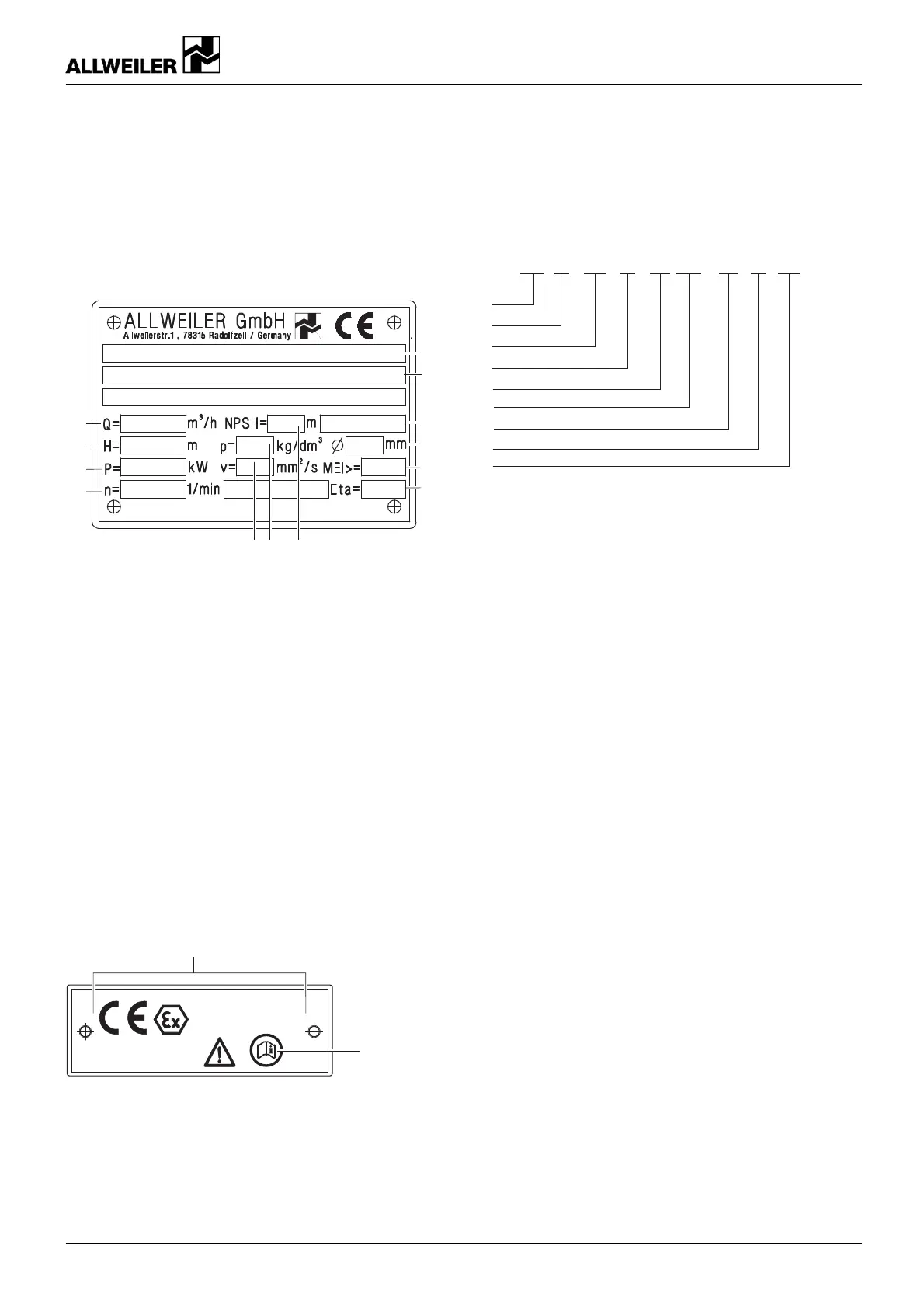
3.1.2 ATEX plate
Technical File No.:
EX9 03 09 45910 002
II 2 G c b Tx
1
2
Fig. 2 ATEX plate
(example)
1 Explosion protection mark
2 Refer
ence to ATEX additional instructions
3.1.3 Pump type code
1
2
3
4
NIT 40 – 200 / 01 / 180 U3D – W3 –38 / 300
5
6
7
8
9
Fig. 3 Pump type code (exa mple)
1Series
2 Size (standard nominal diameter)
3 Nominal impeller diameter
4 Hydraulic number
5 Actual impeller diameter [mm]
6 Shaft seal
7 Material key
8 Stub shaft bore hole diamete r [mm]
9 Outer diameter of motor bell housing o r intermediate
ring or flange size of electric motor
160-282/0 – 550 154 BA-2017.03 en-US NIT series 9