Maintenance
7.4 Installing
NOTE
Material damage caused by knocks and bumps!
Do not knock or hit any components of the pump.
7.4.1 Installation of the pump
Reinstall the components concentricall y, without canting,
in accord ance with t h e markings made.
WARNING
Risk of injury due to heavy components!
Pay attention to the component weight. Lift and transport
heavy components using suitable lifting gear.
Set down c o mp onents safely and secure them against
overturning or rolling away.
WARNING
Risk of injury during assembly!
Install spring-loaded co mponents carefully (e.g. me chan-
ical seal, tensioned be aring, valves etc.), as components
can be ejected by the spring tension.
Observe the manufacturer's specifi cations (e.g. for the
motor, coupling, mechanica l seal, blocking pressure sys-
tem, cardan shaft, drives, belt drive etc.).
NOTE
Material damage due to unsuitable components!
Always replace lo st or damaged screws with screws o f the
same strength (→ 9.2.5 Tightening t orques, Page 37).
Only replace s eals with seals of the same material.
1. Observe the following during the installation:
– Replace wo rn parts with genuine spare pa rts.
– Replace seals, inserting them so that they cannot
rotate.
– Maintain the specified tightening torques
(→ 9.2.5 Tightening torques, Page 37).
2. Clean all parts (→ 9.2.6 Cleaning agents, Page 37). Do
not remove any prepared markings.
3. Install the pump (→ sectional drawing).
4. Install the pump in the system (→ 5 S etup and connection,
Page 14).
7.4.2 Installation of the flanged motor
NOTE
Damage due to incorrect installation!
Ensure that no excessive axial forces are applied to the
pump shaft.
Ensure that the stub shaft rests flush against the collar of
the motor shaft.
Stub shaft, free from oil and grease
The shaft key is not required for installation up to a stub
shaft bore hole diameter of 55 mm.
Stub shaft bore hole diameter (→ 3.1.3 Pump t ype code,
Page 9).
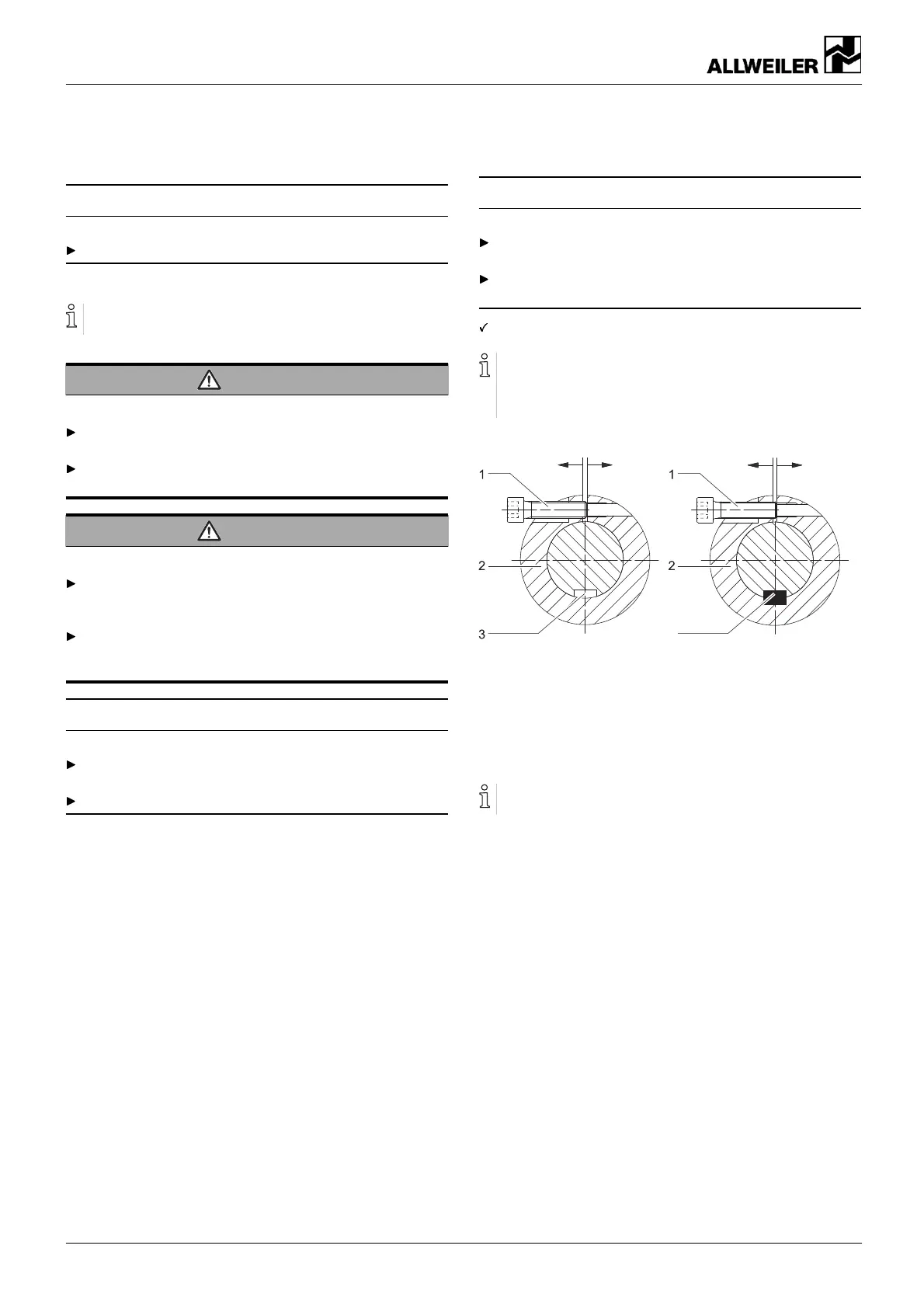
4
Fig. 11 Wideni ng the stub shaft
1 Socket head cap screw
2Stubshaft
3 Shaft key groove of motor shaft
4 Shaft key (from stub shaft bore hole diameter 60 mm)
Tighten the jack screw with a screwdriver without applying
any excessive force.
1. Widening the stub shaft (220.xx):
– Screw the M10 x 40 or M12 x 40 jack screw (not
included in the scope of delivery) into the stub shaft.
2. From stub shaft bore hole diameter 60 mm: insert the shaft
key.
3. Turn the motor shaft so that the slot of the stub shaft is
opposite the shaft k ey groove of the motor shaft.
26 NIT series BA-2017.03 en-U S 160-282/ 0 – 550 154