Maintenance
7.3.1 Returning the pump to the manufacturer
Pump unpressurized
Pump completely empty
Electrical connections isolated and motor secured against
switch-on
Pump cooled down
Auxiliary systems shut down, unpressurized and emptied
Manometer lines, manometer and fi xtures dismounted
Enclose a truthfully and fully completed document of
compliance when returning pumps or individual parts to
the manufacturer (→ 9.4 Declaration of harmlessness,
Page 40).
Repair carried out
Measure for return
...at the customer's
premises
Return the defective
component to the
manufacturer.
...at the
manufacturer's
premises
Flush the pump and
decontaminate it if it was
used to pump hazard ous
media.
Return the complete pump
(not disassembled) to the
manufacturer.
...at the
manufacturer's
premises for
warranty repairs
Only in the event of
hazardous pumped media:
flush and decontaminate the
pump.
Return the complete pump
(not disassembled) to the
manufacturer.
Tab. 11 Measures for re tur n
7.3.2 Preparations for d ismounting
Pump unpressurized
Pump completely empty, flushed and decontaminated
Electrical connections isolated and motor secured against
switch-on
Pump cooled down
Auxiliary systems shut down, depressur
ized and emptied
Manometer lines, manometer and fi xtures dismounted
Safety guarding removed
In production, the pumps
are constructed to a standard
process. The slide-in u
nit can be removed without remov-
ing the volute casing a
nd piping.
1. When dismounting, observe the following:
– Mark the precise orientation and position of all compo-
nents before dismounting.
– Dismantle components concentrically without canting.
2. Dismount the pump (→ sectional drawing).
7.3.3 Removal of the flanged motor
WARNING
Risk of injury due to overturning motor!
Secure the motor to preven t overturning before working on
thestubshaft.
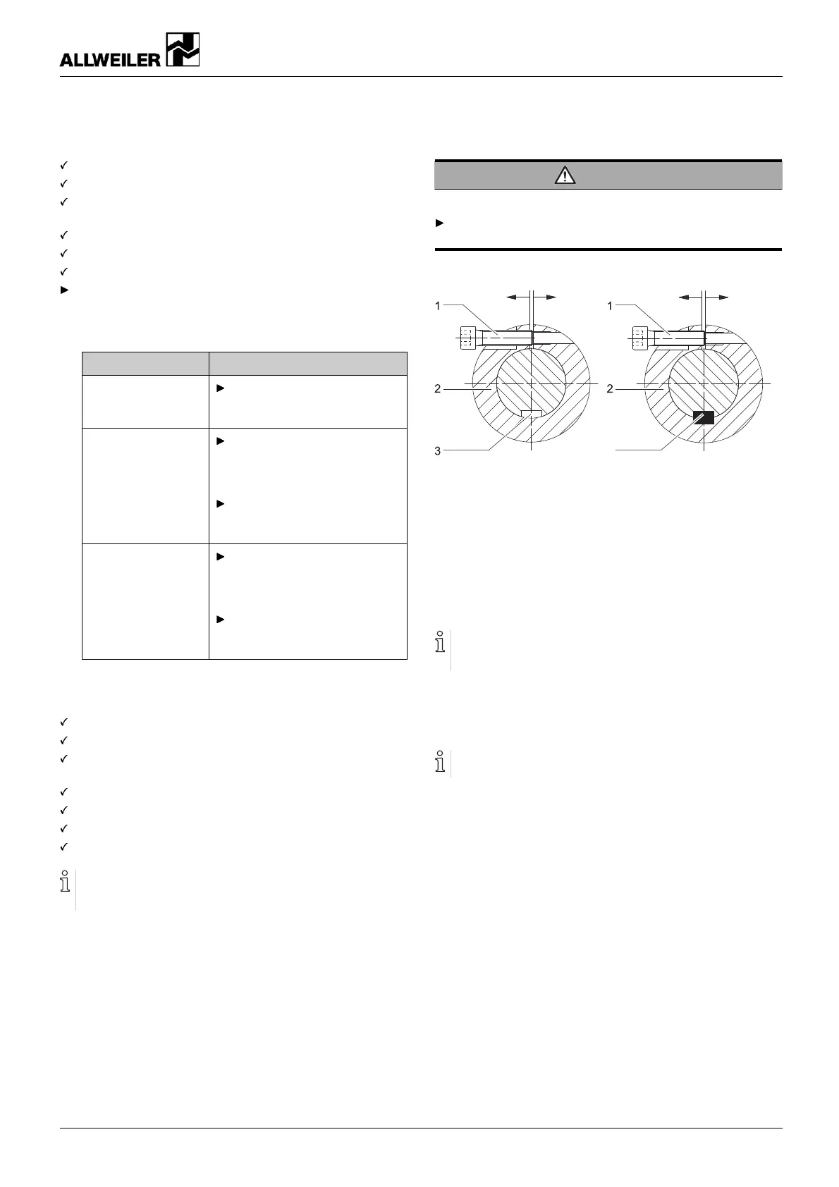
4
Fig. 10 Widening the stub shaft
1 Socket head cap screw
2 Stub s haft
3 Shaft key groove of motor shaft
4 Shaft key (from stub shaft bore hole diameter 60 mm)
1. Remove one half of the guard sheet (686.01) from the
motor bell housing (341.01).
The Allen key required to undo the socket head cap screw
(914.14) is inserted in one of the two cast-in recesses in
the motor bell housing.
2. Undo the socket head cap screw (914.14) on the stub shaft
(220.xx) and unscrew it completely (→ 9.1 Sectional draw-
ings, Page 3 1).
Tighten the jack screw with a screwdriver without applying
any excessive force.
3. Widening the stub shaft (220.xx):
– Screw the M10 x 40 or M 12 x 40 jack screw (not
included in the scope of delivery) into the stub shaft.
4. Remove the flanged motor.
160-282/0 – 550 154 BA-2017.03 en-US NIT series 25