Maintenance
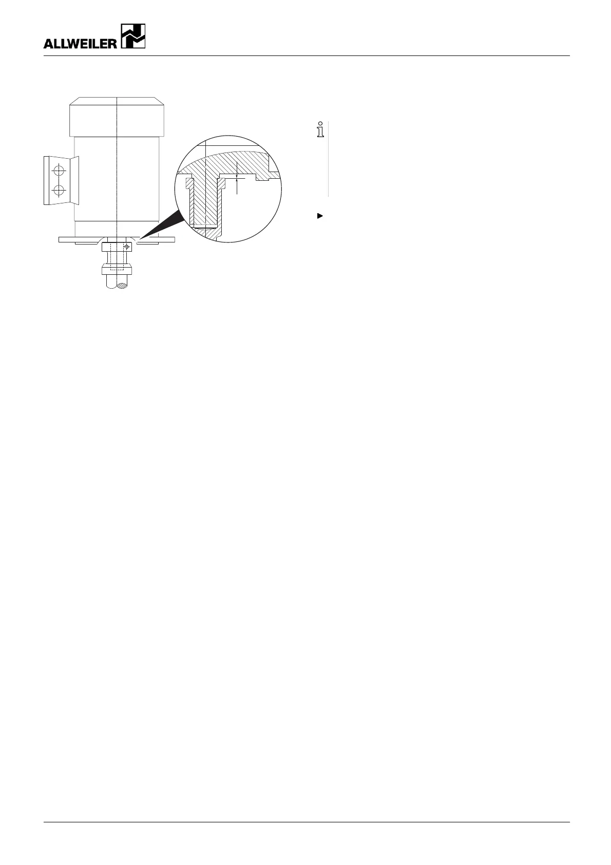
0 mm
Fig. 12 Motor assembly
4. Carefully, slide on the motor u ntil the stub shaft rests flush
against the co llar o f the motor sha ft.
– Ensure that no excessive axial forces are applied to the
pump shaft.
5. Screw in the motor bolts and tighten them.
– Ensure that the stub shaft continues r esting flush
against the collar of t he motor shaft.
6. Undo and un screw the jack screw. Screw in the socket
head cap screw (914.14) and t ighten it with a torque wrench
(→ 9.2.5 Tightening torques, Page 37).
7. Install the safety equipment:
– Guard sheet for t he motor bell housin g
8. Install the auxiliary devices:
– Manometer lines and h oldings on the pump
– Auxiliary piping
9. Tu rn the stub shaft by hand:
– Ensure the stub shaft can be turned easily without pres-
sure points.
7.5 Ordering spare parts
For trouble-free replacement in the event of faults, we rec-
ommend keeping entire slide-in u nits or spare pumps avail-
able on site.
The application guidelines confo rming to DIN 24296 rec-
ommend provisio ning for two years of continuous use
(→ 9.3 Spare parts for two y ears of continuou s operatio n
according to DIN 24296, Page 39).
Have the following information ready to hand when order-
ing spare parts (→ type plate):
–Pumptype
– Pump numbe r
– Year of manufacture
– Part number
– Designation
– Quantity
160-282/0 – 550 154 BA-2017.03 en-US NIT series 27