Setup and connection
5.3 Installing in the pipe
5.3.1 Keeping the piping clean
NOTE
Material damage due to impurities in the pump!
Make sure no impurities can enter the pump.
1. Clean all pipin g parts and armatures pri or to assembly.
2. Ensure no flan ge seals protrude inwards.
3. Remove any blind fl anges, plugs, protective foils and/or
protective paint from flanges.
5.3.2 Install pump aggregate
NOTE
Material damage du e to excessive for ces!
Makesurethepipeisabletobeartheweightofthepump
aggregate and all operating forces which occur.
Make sure that the distance and alignment of the pipe
flanges comply with the pump dimensi ons (→ setup draw-
ing).
1. Remove the transport and se aling covers from the pump.
2. Lift the pump aggregate (→ 4.1 Transport, Page 12).
3. Raise the pump aggregate betwee n the pipe ends.
– Observe the pumping direction of the pump.
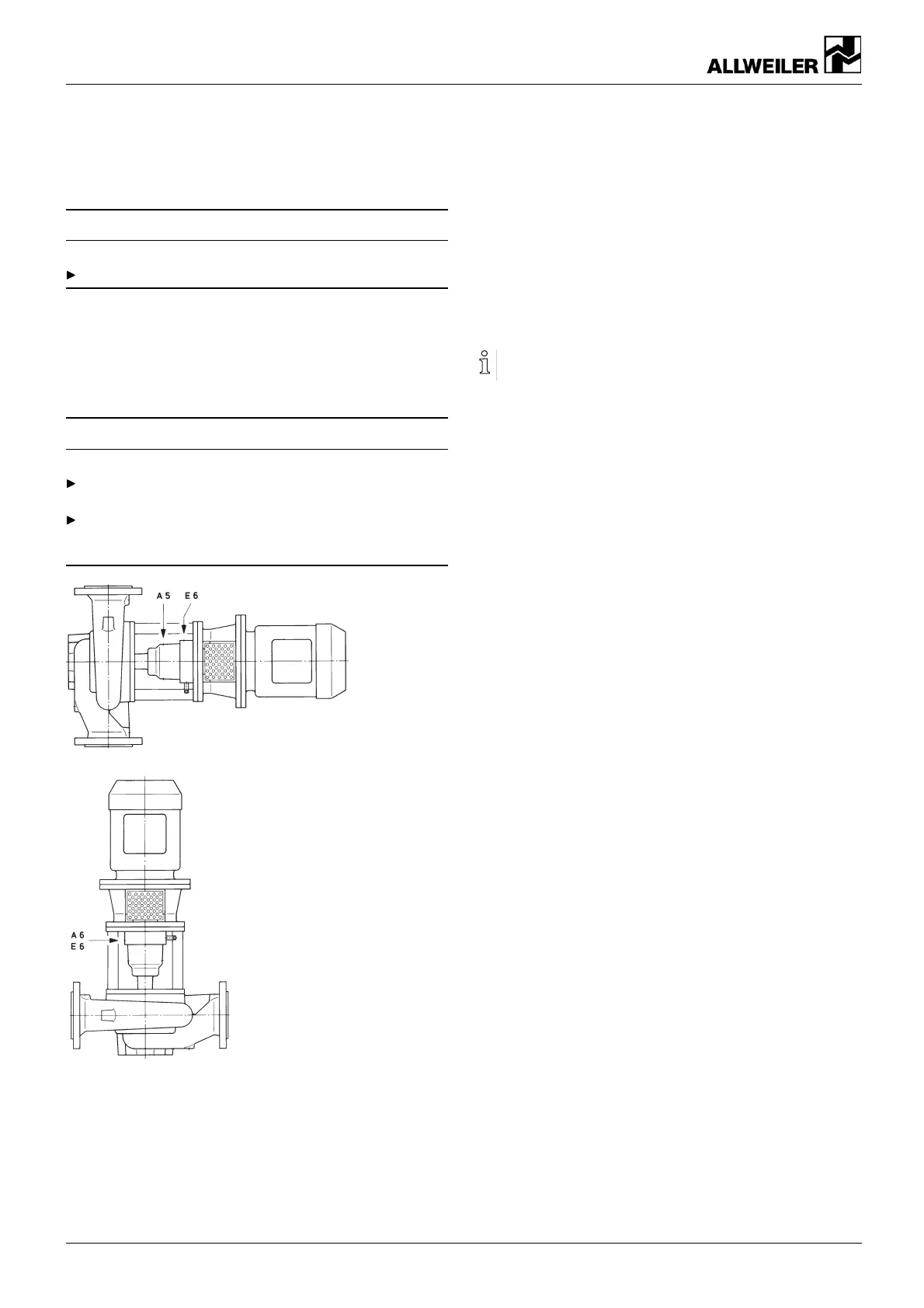
– Horizontal installation: Motor at top.
– Vertical installation: Connections (A5, E6) at top.
4. Screw t he suction flange and discharge flange to the pipe.
– Maintain the prescribed tightening torques
(→ 9.2.5 Tightening torques, Page 37).
5.3.3 Installing auxiliary pipes (if available)
Follow the manufacturers' specifications for any available
auxiliary systems.
1. Connect the auxiliary pipes to the auxiliary connections s o
that they are stress-free and do not leak (→ setup drawing).
2. To a void air pockets, run the pipes with a continuous slope
up to the pump.
3. On versions with quenching:
– Feed the quenching egress (QO2) into a clo sed con-
tainer.
16 NIT series BA-2017.03 en-U S 160-282/ 0 – 550 154