Setup and connection
5.4 Installing the motor
Only necessary if the pump aggregate is assembled on site
WARNING
Risk of injury due to overturning motor!
Secure the motor to preven t overturning before working on
the stub shaft.
NOTE
Damage due to incorrect installation!
Ensure that no excessive axial forces are applied to the
pump shaft.
Ensure that the stub shaft rests flush against the collar of
the motor shaft.
Stub shaft, free from oil and grease
The shaft key is not required for installation up to a stub
shaft bore hole diameter of 55 mm.
Stub shaft bore hole diameter (→ 3.1.3 Pump type code,
Page 9).
4
Fig. 8 Widening the stub shaft
1 Socket head cap screw
2 Stub s haft
3 Shaft key groove of motor shaft
4 Shaft key (from stub shaft bore hole diameter 60 mm)
1. Observe the foll owing during installation:
– Adhere to the specified tightening torques
(→ 9.2.5 Tightening torques, Page 37).
2. Remove the retaining clamp for the stub shaft from the
motor bell housing (341.01):
– Undo the b olts/nuts (901.10) for this purpose
(→ 9.1 Section al drawings, Page 31).
3. Undo the hexagon head bolts (901.07) and remove the
washers (554.07).
4. Remove one half of the guard sheet (686.01) from the
motor bell housing (341.01).
The Allen key required to undo the socket head cap screw
(914.14) is inserted in one of the two cast-in recesses in
the motor bell housing.
5. Undo the socket head cap screw (914.14) on the stub shaft
(220.xx) and unscrew it completely (→ 9.1 Sectional draw-
ings, Page 3 1).
Tighten the jack screw with a screwdriver without applying
any excessive force.
6. Widening the stub shaft (220.xx):
– Screw the M10 x 40 or M 12 x 40 jack screw (not
included in the scope of delivery) into the stub shaft.
7. From stub shaft bore hole diameter 60 mm: insert the shaft
key.
8. Turn the motor shaft so that the slot of the stub shaft is
opposite the shaft key groove of t he motor shaft.
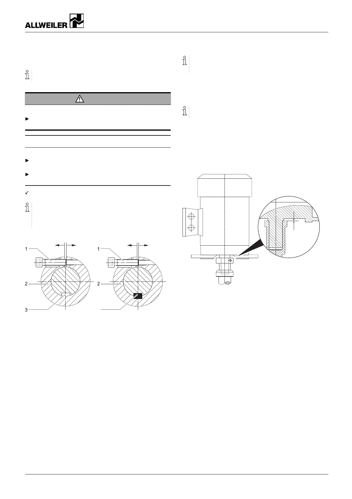
0 mm
Fig. 9 Motor assembly
9. Carefully, slide on the motor u ntil the stub shaft rests flush
against the co llar o f the motor sha ft.
– Ensure that no excessive axial forces are a
pplied to the
pump shaft.
10. Screw in the motor bolts and tighte n them.
– Ensure that the stub shaft continues r esting flush
against the collar of t he motor shaft.
11. Undo and un screw the jack screw. Screw in the socket
head cap screw (914.14) and t ighten it with a torque wrench
(→ 9.2.5 Tightening torques, Page 37).
12. Install the safety equipment:
– Guard sheet for the motor bell hou
sing
13. Install the auxiliary devices:
– Manometer lines and h oldings on the pump
– Auxiliary piping
14. Turn the stub shaft by hand:
– Ensure the stub shaft can be turned easily without pres-
sure points.
160-282/0 – 550 154 BA-2017.03 en-US NIT series 17