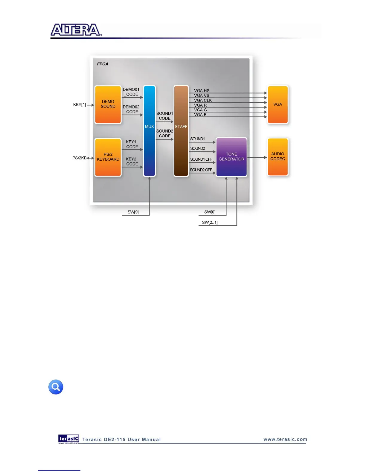
Figure 6-23 Block diagram of the Music Synthesizer design
Demonstration Setup, File Locations, and Instructions
Project directory: DE2_115_Synthesizer
Bit stream used: DE2_115_Synthesizer.sof or DE2-115_Synthesizer.pof
Connect a PS/2 Keyboard to the DE2-115 board.
Connect the VGA output of the DE2-115 board to a VGA monitor (both LCD and CRT type of
monitors should work)
Connect the lineout of the DE2-115 board to a speaker.
Load the bit stream into FPGA by executing
DE2_115_Synthesizer\demo_batch\DE2_115_Synthesizer.bat file
Make sure all the switches (SW[9:0]) are set to 0 (Down Position)
Press KEY1 on the DE2-115 board to start the music demo
Press KEY0 on the DE2-115 board to reset the circuit
Note: If the HSMC loopback adapter is mounted, the I2C_SCL will be directly routed back
to I2C_SDA. Because audio chip, TV decoder chip and HSMC share one I2C bus, therefore
audio and video chip won’t function correctly.