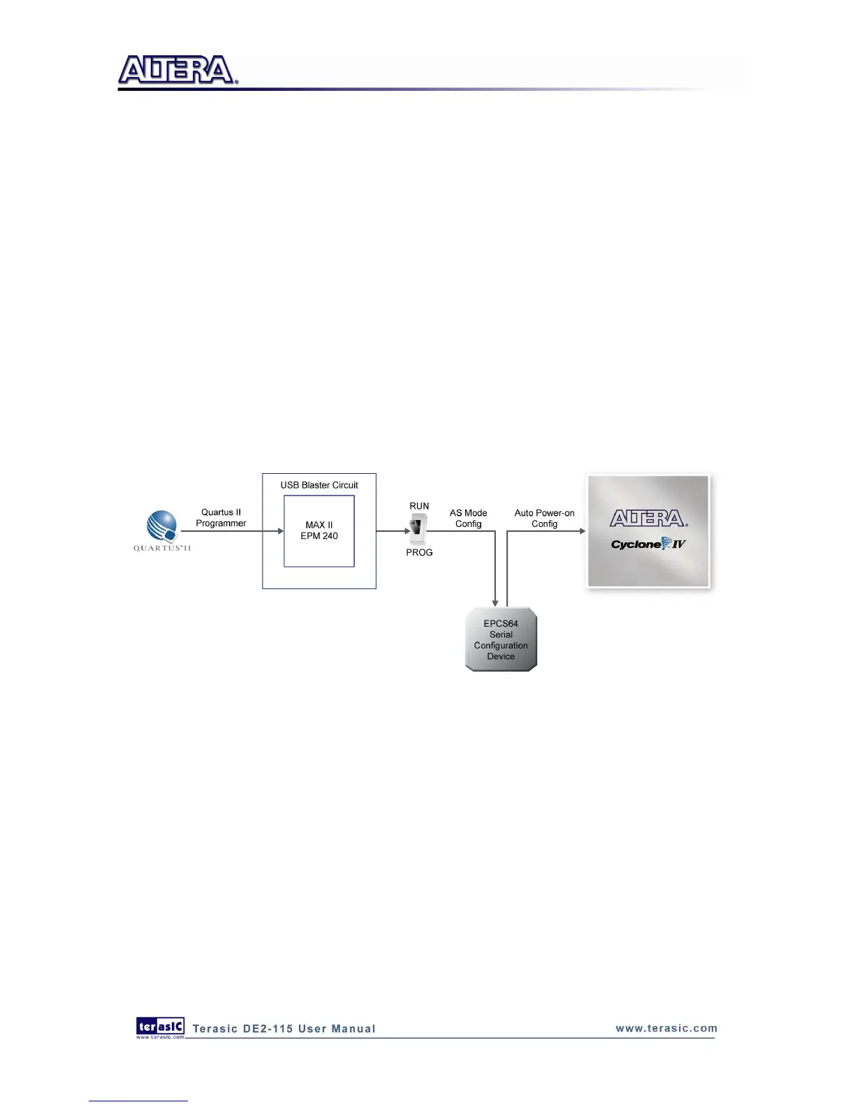
Configuring the EPCS64 in AS Mode
Figure 4-5 illustrates the AS configuration setup. To download a configuration bit stream into the
EPCS64 serial configuration device, perform the following steps:
Ensure that power is applied to the DE2-115 board.
Connect the supplied USB cable to the USB Blaster port on the DE2-115 board (See Figure
4-5)
Configure the JTAG programming circuit by setting the RUN/PROG slide switch (SW19) to the
PROG position.
The EPCS64 chip can now be programmed by using the Quartus II Programmer to select a
configuration bit stream file with the .pof filename extension.
Once the programming operation is finished, set the RUN/PROG slide switch back to the RUN
position and then reset the board by turning the power switch off and back on; this action causes
the new configuration data in the EPCS64 device to be loaded into the FPGA chip.
Figure 4-5 The AS configuration scheme
4
4
.
.
2
2
U
U
s
s
i
i
n
n
g
g
P
P
u
u
s
s
h
h
-
-
b
b
u
u
t
t
t
t
o
o
n
n
s
s
a
a
n
n
d
d
S
S
w
w
i
i
t
t
c
c
h
h
e
e
s
s
The DE2-115 board provides four push-button switches as shown in Figure 4-6. Each of these
switches is debounced using a Schmitt Trigger circuit, as indicated in Figure 4-7. The four outputs
called KEY0, KEY1, KEY2, and KEY3 of the Schmitt Trigger devices are connected directly to the
Cyclone IV E FPGA. Each push-button switch provides a high logic level when it is not pressed,
and provides a low logic level when depressed. Since the push-button switches are debounced, they
are appropriate for using as clock or reset inputs in a circuit.