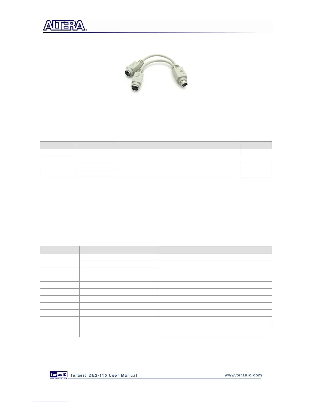
Figure 4-26 Y-Cable use for both Keyboard and Mouse
Table 4-19 PS/2 Pin Assignments
PS/2 Clock (reserved for second PS/2 device)
PS/2 Data (reserved for second PS/2 device)
4
4
.
.
1
1
4
4
G
G
i
i
g
g
a
a
b
b
i
i
t
t
E
E
t
t
h
h
e
e
r
r
n
n
e
e
t
t
T
T
r
r
a
a
n
n
s
s
c
c
e
e
i
i
v
v
e
e
r
r
The DE2-115 board provides Ethernet support via two Marvell 88E1111 Ethernet PHY chips. The
88E1111 chip with integrated 10/100/1000 Mbps Gigabit Ethernet transceiver support
GMII/MII/RGMII/TBI MAC interfaces. Table 4-20 describes the default settings for both chips.
Figure 4-27 shows the connection setup between the Gigabit Ethernet PHY (ENET0) and FPGA.
Table 4-20 Default Configuration for Gigabit Ethernet
PHY Address in MDIO/MDC Mode
10000 for Enet0;10001 for Enet1
1-Default Register 4.11:10 to 11
Auto negotiation configuration
for copper modes
1110-Auto-neg, advertise all capabilities, prefer
master
Hardware Configuration Mode
1011/1111 RGMII to copper/GMII to copper
Disable fiber/copper interface
0-Select MDC/MDIO interface
1-INTn signal is active LOW
0-50 ohm termination for fiber
Here only RGMII and MII modes are supported on the board (The factory default mode is RGMII).
There is one jumper for each chip for switching work modes from RGMII to MII (See Figure 4-28).