4
4
.
.
4
4
U
U
s
s
i
i
n
n
g
g
t
t
h
h
e
e
7
7
-
-
s
s
e
e
g
g
m
m
e
e
n
n
t
t
D
D
i
i
s
s
p
p
l
l
a
a
y
y
s
s
The DE2-115 Board has eight 7-segment displays. These displays are arranged into two pairs and a
group of four, behaving the intent of displaying numbers of various sizes. As indicated in the
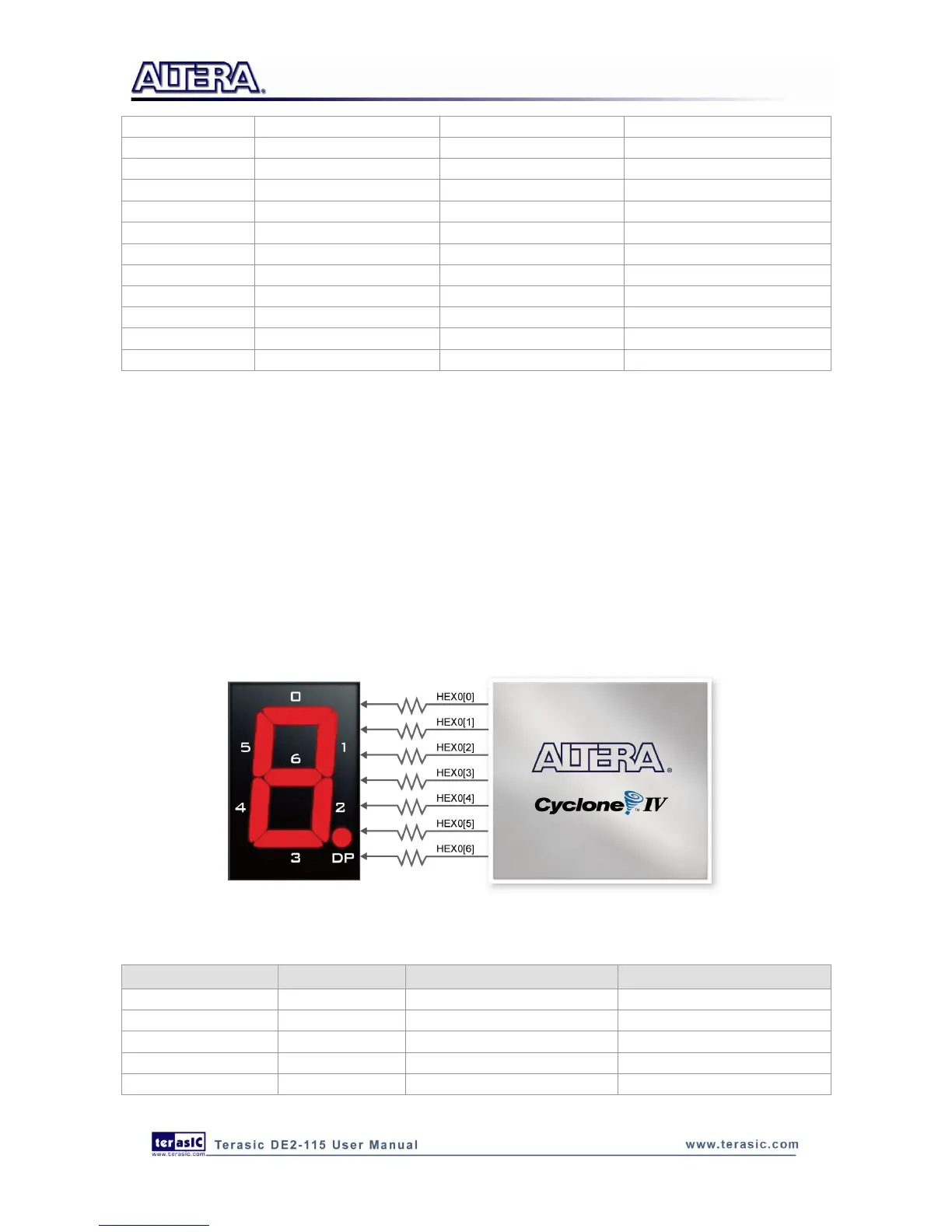
schematic in Figure 4-10, the seven segments (common anode) are connected to pins on Cyclone
IV E FPGA. Applying a low logic level to a segment will light it up and applying a high logic level
turns it off.
Each segment in a display is identified by an index from 0 to 6, with the positions given in Figure
4-10. Table 4-4 shows the assignments of FPGA pins to the 7-segment displays.
Figure 4-10 Connections between the 7-segment display HEX0 and Cyclone IV E FPGA
Table 4-4 Pin Assignments for 7-segment Displays