EasyManua.ls Logo

Altera DE2-115 - Using IR

Altera DE2-115
116 pages
Print Icon
To Next Page IconTo Next Page
To Previous Page IconTo Previous Page
Loading...
62
OTG_DATA[8]
PIN_H3
ISP1362 Data[8]
3.3V
OTG_DATA[9]
PIN_H4
ISP1362 Data[9]
3.3V
OTG_DATA[10]
PIN_G1
ISP1362 Data[10]
3.3V
OTG_DATA[11]
PIN_G2
ISP1362 Data[11]
3.3V
OTG_DATA[12]
PIN_G3
ISP1362 Data[12]
3.3V
OTG_DATA[13]
PIN_F1
ISP1362 Data[13]
3.3V
OTG_DATA[14]
PIN_F3
ISP1362 Data[14]
3.3V
OTG_DATA[15]
PIN_G4
ISP1362 Data[15]
3.3V
OTG_CS_N
PIN_A3
ISP1362 Chip Select
3.3V
OTG_RD_N
PIN_B3
ISP1362 Read
3.3V
OTG_WR_N
PIN_A4
ISP1362 Write
3.3V
OTG_RST_N
PIN_C5
ISP1362 Reset
3.3V
OTG_INT[0]
PIN_A6
ISP1362 Interrupt 0
3.3V
OTG_INT[1]
PIN_D5
ISP1362 Interrupt 1
3.3V
OTG_DACK_N[0]
PIN_C4
ISP1362 DMA Acknowledge 0
3.3V
OTG_DACK_N[1]
PIN_D4
ISP1362 DMA Acknowledge 1
3.3V
OTG_DREQ[0]
PIN_J1
ISP1362 DMA Request 0
3.3V
OTG_DREQ[1]
PIN_B4
ISP1362 DMA Request 1
3.3V
OTG_FSPEED
PIN_C6
USB Full Speed, 0 = Enable, Z = Disable
3.3V
OTG_LSPEED
PIN_B6
USB Low Speed, 0 = Enable, Z = Disable
3.3V
4
4
.
.
1
1
8
8
U
U
s
s
i
i
n
n
g
g
I
I
R
R
The DE2-115 provides an infrared remote-control receiver Module (model: IRM-V538N7/TR1),
whose datasheet is offered in the DE2_115_datasheets\IR_Receiver folder on DE2-115 system CD.
Note that for this all-in-one receiver module, it is only compatible with the 38KHz carrier Standard,
with a maximum data rate of about 4kbps for its product information. The accompanied remote
controller with an encoding chip of uPD6121G is very suitable of generating expected infrared
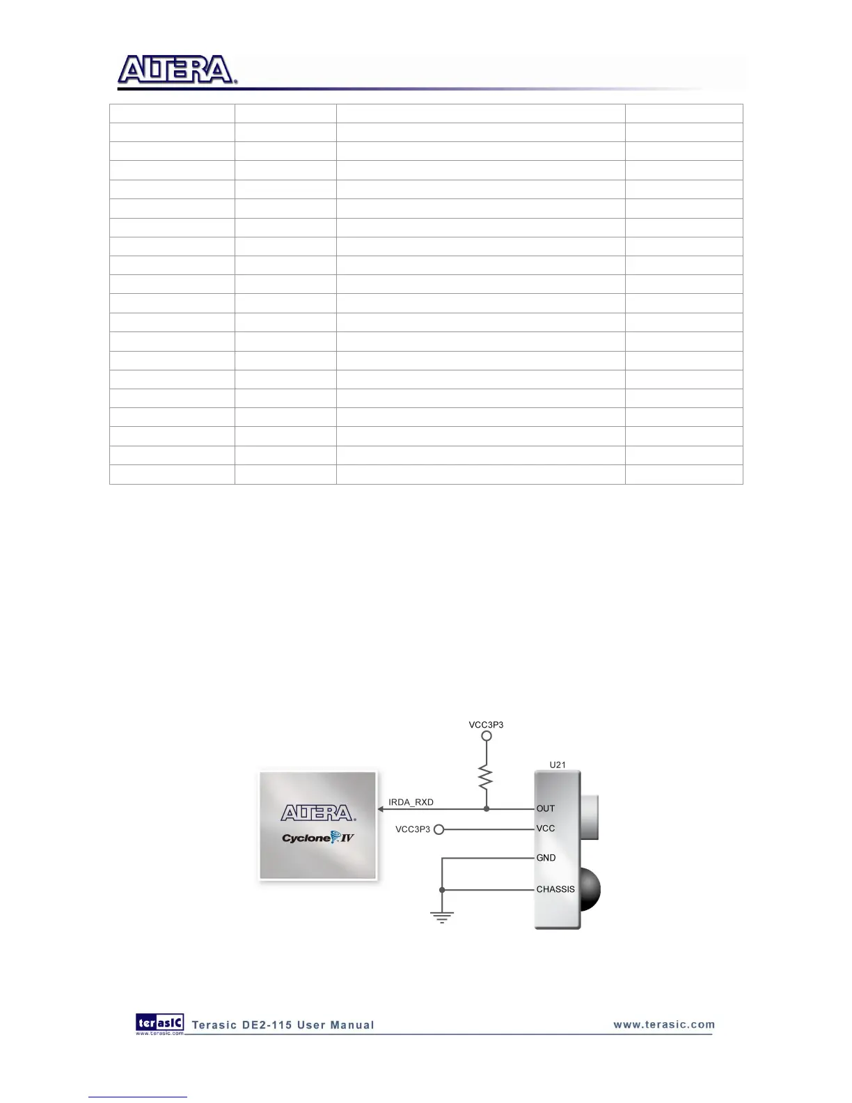
signals. Figure 4-32 shows the related schematic of the IR receiver, and the pin assignments of the
associated interface are listed in Table 4-26.
Figure 4-32 Connection between FPGA and IR

Table of Contents

Related product manuals