Figure 4-8 Connections between the slide switches and Cyclone IV E FPGA
4
4
.
.
3
3
U
U
s
s
i
i
n
n
g
g
L
L
E
E
D
D
s
s
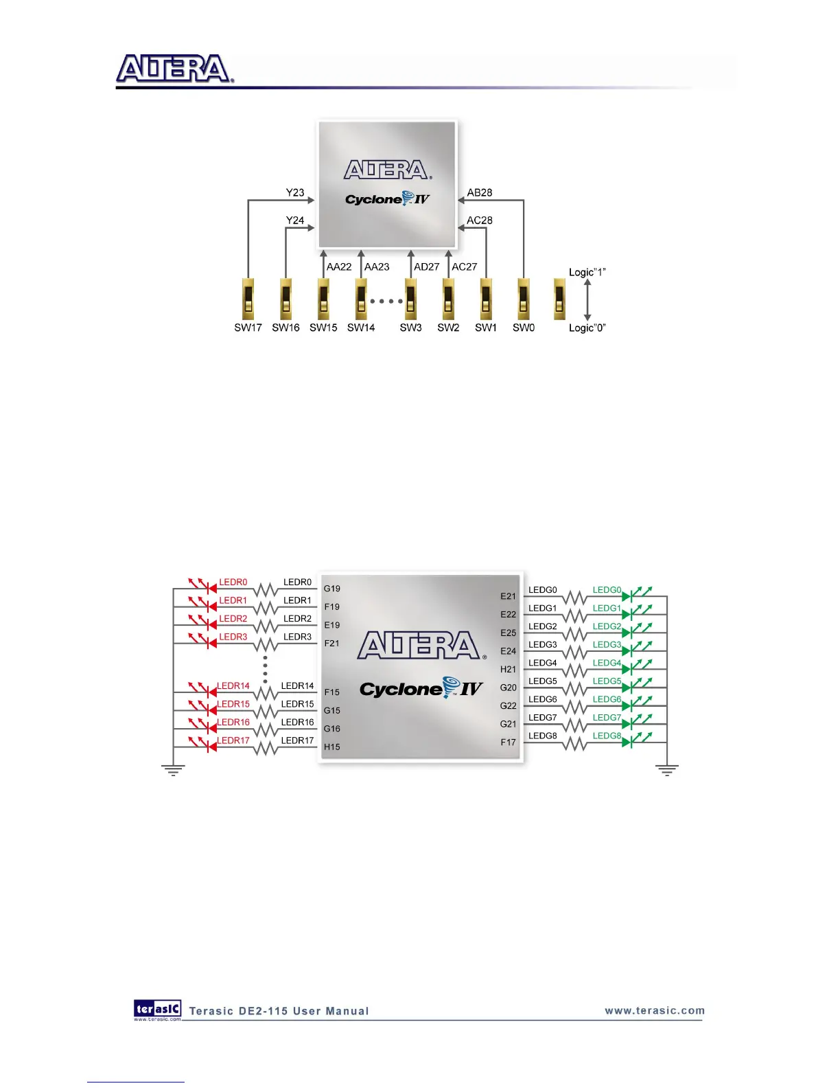
There are 27 user-controllable LEDs on the DE2-115 board. Eighteen red LEDs are situated above
the 18 Slide switches, and eight green LEDs are found above the push-button switches (the 9th
green LED is in the middle of the 7-segment displays). Each LED is driven directly by a pin on the
Cyclone IV E FPGA; driving its associated pin to a high logic level turns the LED on, and driving
the pin low turns it off. Figure 4-9 shows the connections between LEDs and Cyclone IV E FPGA.
Figure 4-9 Connections between the LEDs and Cyclone IV E FPGA
A list of the pin names on the Cyclone IV E FPGA that are connected to the slide switches is given
in Table 4-1. Similarly, the pins used to connect to the push-button switches and LEDs are
displayed in Table 4-2 and Table 4-3, respectively.