EasyManua.ls Logo

Altera DE2-115 - Using 14-Pin General Purpose I;O Connector

Altera DE2-115
116 pages
Print Icon
To Next Page IconTo Next Page
To Previous Page IconTo Previous Page
Loading...
50
GPIO[29]
PIN_AF26
GPIO Connection DATA[29]
Depending on JP6
GPIO[30]
PIN_AE20
GPIO Connection DATA[30]
Depending on JP6
GPIO[31]
PIN_AG23
GPIO Connection DATA[31]
Depending on JP6
GPIO[32]
PIN_AF20
GPIO Connection DATA[32]
Depending on JP6
GPIO[33]
PIN_AH26
GPIO Connection DATA[33]
Depending on JP6
GPIO[34]
PIN_AH23
GPIO Connection DATA[34]
Depending on JP6
GPIO[35]
PIN_AG26
GPIO Connection DATA[35]
Depending on JP6
4
4
.
.
9
9
U
U
s
s
i
i
n
n
g
g
1
1
4
4
-
-
p
p
i
i
n
n
G
G
e
e
n
n
e
e
r
r
a
a
l
l
P
P
u
u
r
r
p
p
o
o
s
s
e
e
I
I
/
/
O
O
C
C
o
o
n
n
n
n
e
e
c
c
t
t
o
o
r
r
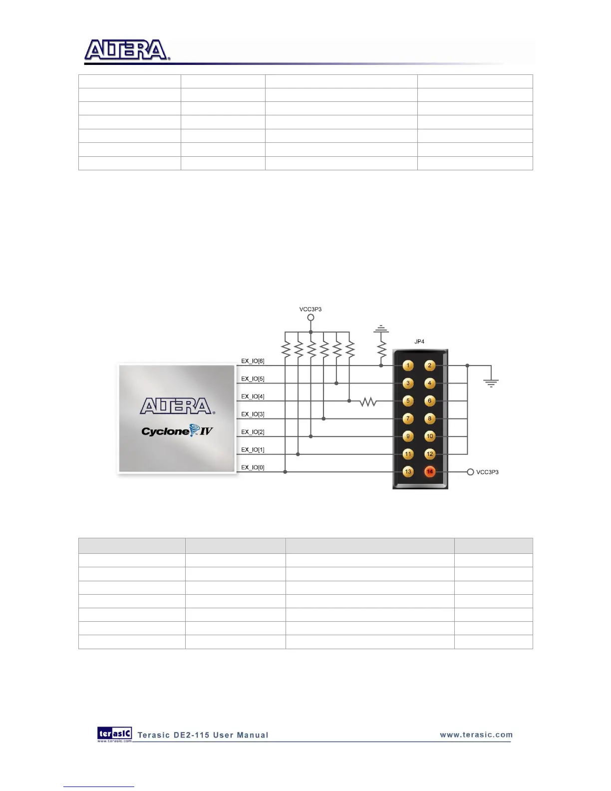
The DE2-115 Board provides 14-pin expansion header. The header connects directly to 7 pins of the
Cyclone IV E FPGA, and also provides DC +3.3V (VCC3P3), and six GND pins as shown in
Figure 4-20. The voltage level of the I/O pins on the 14-pin expansion header is 3.3V. Finally,
Table 4-13 shows the pin assignments for I/O connections.
Figure 4-20 Connections between FPGA and 14-pin general purpose I/O
Table 4-13 Pin Assignments for General Purpose I/Os
Signal Name
FPGA Pin No.
Description
I/O Standard
EX_IO[0]
PIN_J10
Extended IO[0]
3.3V
EX_IO[1]
PIN_J14
Extended IO[1]
3.3V
EX_IO[2]
PIN_H13
Extended IO[2]
3.3V
EX_IO[3]
PIN_H14
Extended IO[3]
3.3V
EX_IO[4]
PIN_F14
Extended IO[4]
3.3V
EX_IO[5]
PIN_E10
Extended IO[5]
3.3V
EX_IO[6]
PIN_D9
Extended IO[6]
3.3V

Table of Contents

Related product manuals