4
4
.
.
1
1
3
3
P
P
S
S
/
/
2
2
S
S
e
e
r
r
i
i
a
a
l
l
P
P
o
o
r
r
t
t
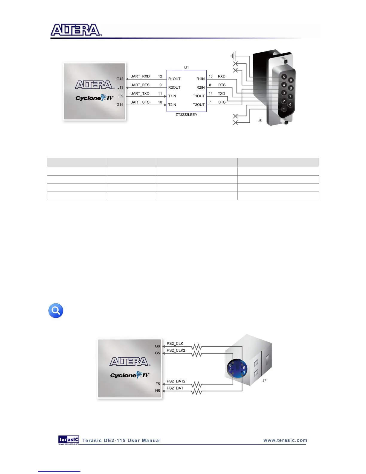
The DE2-115 board includes a standard PS/2 interface and a connector for a PS/2 keyboard or
mouse. Figure 4-25 shows the schematic of the PS/2 circuit. In addition, users can use the PS/2
keyboard and mouse on the DE2-115 board simultaneously by plugging an extension PS/2 Y-Cable
(See Figure 4-26). Instructions for using a PS/2 mouse or keyboard can be found by performing an
appropriate search on various educational websites. The pin assignments for the associated interface
are shown in Table 4-19.
Note: If users connect only one PS/2 equipment, the PS/2 interface between FPGA I/O
should be “PS2_CLK” and “PS2_DAT”.
Figure 4-25 Connection between FPGA and PS/2