EasyManua.ls Logo

Altera DE2-115 - TV Decoder; Implementing a TV Encoder

Altera DE2-115
116 pages
Print Icon
To Next Page IconTo Next Page
To Previous Page IconTo Previous Page
Loading...
60
Note: If the HSMC loopback adapter is mounted, the I2C_SCL will be directly routed back
to I2C_SDA. Because audio chip, TV decoder chip and HSMC share one I2C bus, therefore
audio and video chip wont function correctly.
Table 4-24 TV Decoder Pin Assignments
Signal Name
FPGA Pin No.
Description
I/O Standard
TD_ DATA [0]
PIN_E8
TV Decoder Data[0]
3.3V
TD_ DATA [1]
PIN_A7
TV Decoder Data[1]
3.3V
TD_ DATA [2]
PIN_D8
TV Decoder Data[2]
3.3V
TD_ DATA [3]
PIN_C7
TV Decoder Data[3]
3.3V
TD_ DATA [4]
PIN_D7
TV Decoder Data[4]
3.3V
TD_ DATA [5]
PIN_D6
TV Decoder Data[5]
3.3V
TD_ DATA [6]
PIN_E7
TV Decoder Data[6]
3.3V
TD_ DATA [7]
PIN_F7
TV Decoder Data[7]
3.3V
TD_HS
PIN_E5
TV Decoder H_SYNC
3.3V
TD_VS
PIN_E4
TV Decoder V_SYNC
3.3V
TD_CLK27
PIN_B14
TV Decoder Clock Input.
3.3V
TD_RESET_N
PIN_G7
TV Decoder Reset
3.3V
I2C_SCLK
PIN_B7
I2C Clock
3.3V
I2C_SDAT
PIN_A8
I2C Data
3.3V
4
4
.
.
1
1
6
6
I
I
m
m
p
p
l
l
e
e
m
m
e
e
n
n
t
t
i
i
n
n
g
g
a
a
T
T
V
V
E
E
n
n
c
c
o
o
d
d
e
e
r
r
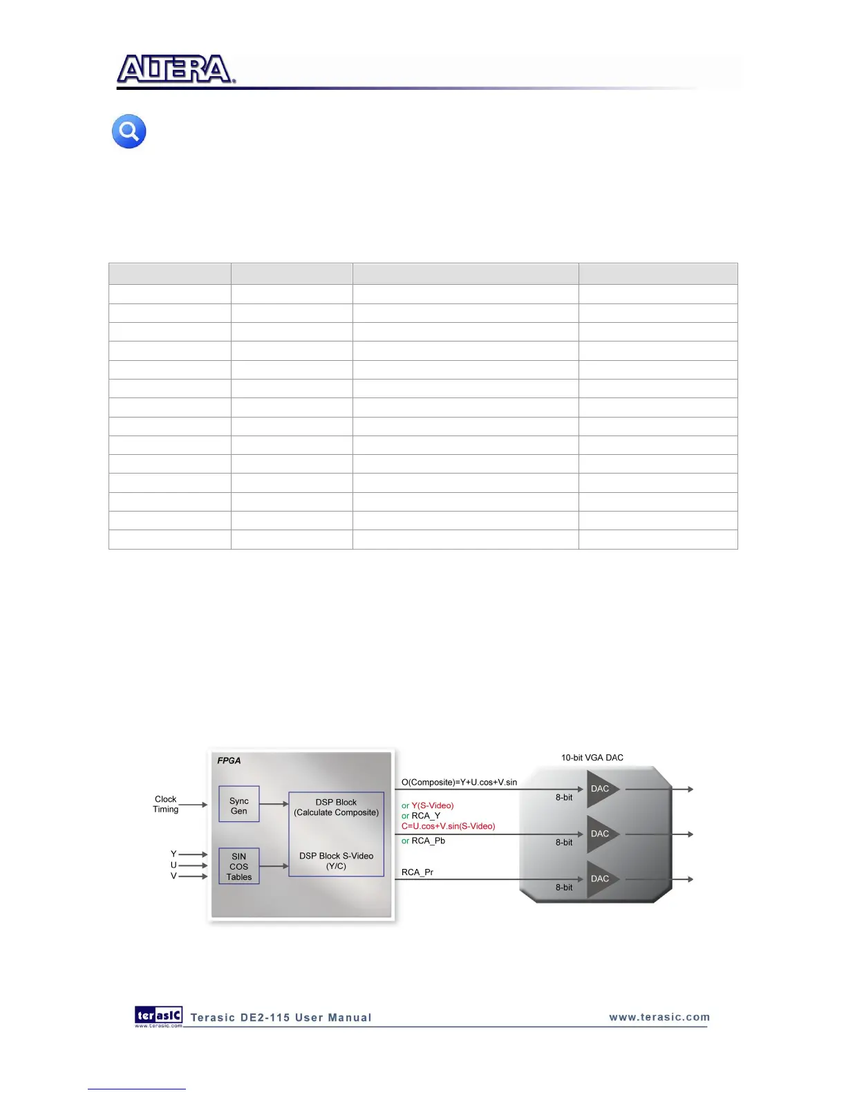
Although the DE2-115 board does not include a TV encoder chip, the ADV7123 (10-bit high-speed
triple ADCs) can be used to implement a professional-quality TV encoder with the digital
processing part implemented in the Cyclone IV E FPGA. Figure 4-30 shows a block diagram of a
TV encoder implemented in this manner.
Figure 4-30 A TV Encoder that uses the Cyclone IV E FPGA and the ADV7123

Table of Contents

Related product manuals