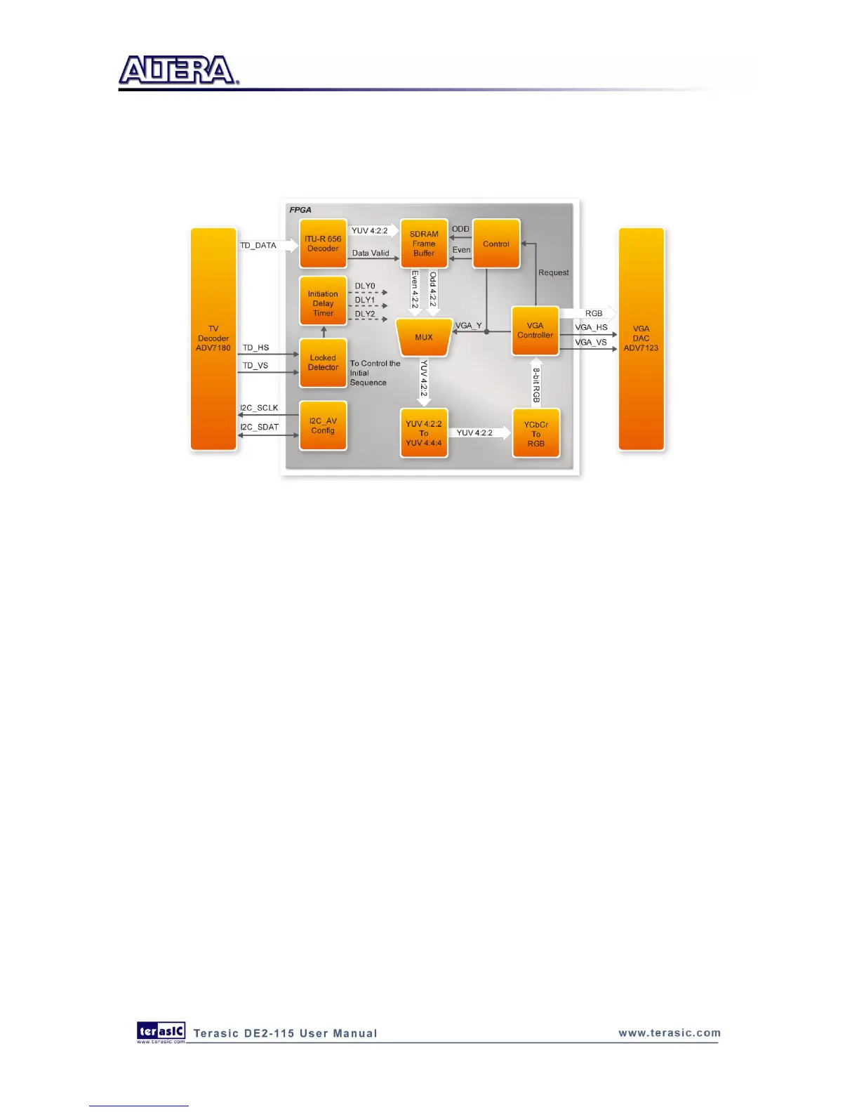
Finally, the YcrCb_to_RGB block converts the YcrCb data into RGB data output. The VGA
Controller block generates standard VGA synchronous signals VGA_HS and VGA_VS to enable
the display on a VGA monitor.
Figure 6-1 Block diagram of the TV box demonstration
Demonstration Setup, File Locations, and Instructions
Project directory: DE2_115_TV
Bit stream used: DE2_115_TV.sof or DE2_115_TV.pof
Connect a DVD player‟s composite video output (yellow plug) to the Video-In RCA jack (J12)
of the DE2-115 board. The DVD player has to be configured to provide:
o NTSC output
o 60Hz refresh rate
o 4:3 aspect ratio
o Non-progressive video
Connect the VGA output of the DE2-115 board to a VGA monitor (both LCD and CRT type of
monitors should work)
Connect the audio output of the DVD player to the line-in port of the DE2-115 board and
connect a speaker to the line-out port. If the audio output jacks from the DVD player are RCA
type, then an adaptor will be needed to convert to the mini-stereo plug supported on the
DE2-115 board; this is the same type of plug supported on most computers
Load the bit stream into FPGA by execute the batch file „de2_115_tv.bat‟ under
DE2_115_TV\demo_batch\ folder
Press KEY0 on the DE2-115 board to reset the circuit