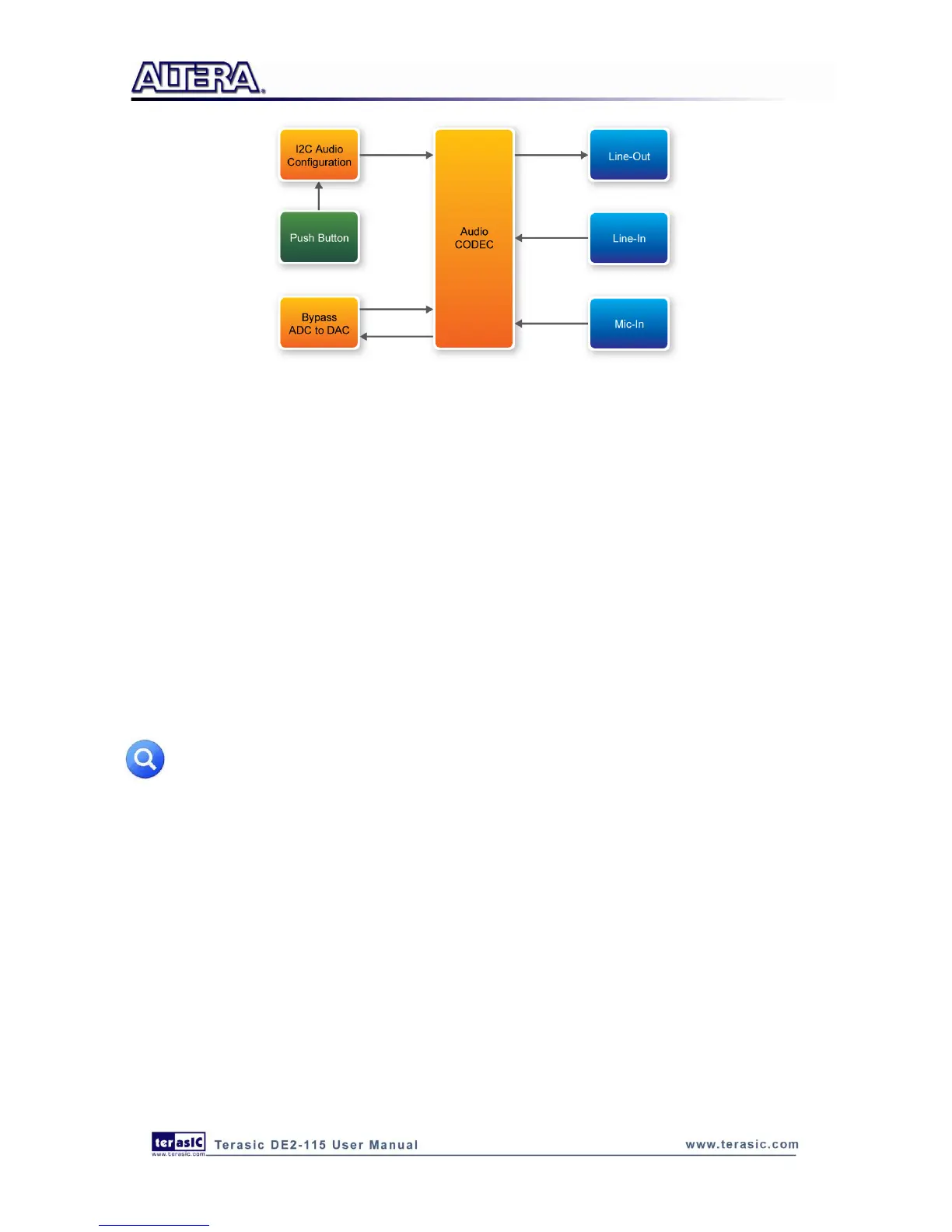
Figure 6-7 Block diagram of the Karaoke Machine demonstration
Demonstration Setup, File Locations, and Instructions
Project directory: DE2_115_i2sound
Bit stream used: DE2_115_i2sound.sof or DE2_115_i2sound.pof
Connect a microphone to the microphone-in port (pink color) on the DE2-115 board
Connect the audio output of a music-player, such as an MP3 player or computer, to the line-in
port (blue color) on the DE2-115 board
Connect a headset/speaker to the line-out port (green color) on the DE2-115 board
Load the bit stream into the FPGA by execute the batch file „DE2_115_i2sound‟ under the
DE2_115_i2sound\demo_batch folder
You should be able to hear a mixture of the microphone sound and the sound from the music
player
Press KEY0 to adjust the volume; it cycles between volume levels 0 to 9
Note: If the HSMC loopback adapter is mounted, the I2C_SCL will be directly routed back
to I2C_SDA. Because audio chip, TV decoder chip and HSMC share one I2C bus, therefore
audio and video chip won’t function correctly.
Figure 6-8 illustrates the setup for this demonstration.