1-20 American-Lincoln
MPV 60
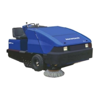
HOPPER COVER LATCH (figure 26)
The hopper has two hinged covers for easy access to the
hopper components may be needed for inspection or
service.
To access the upper hopper cover (single latch at top)
1. Press on the rear portion of the latch
2. Lift and turn the latch 90°
To access the lower hopper cover (two latches at bottom)
1. Press on the rear portion of each latch (one at a time)
2. Lift and rotate each latch 180°
To close hopper covers:
1. Lower covers carefully
2. Turn latches (in the opposite direction than when
opening)
3. Press the latches down into the recess to lock
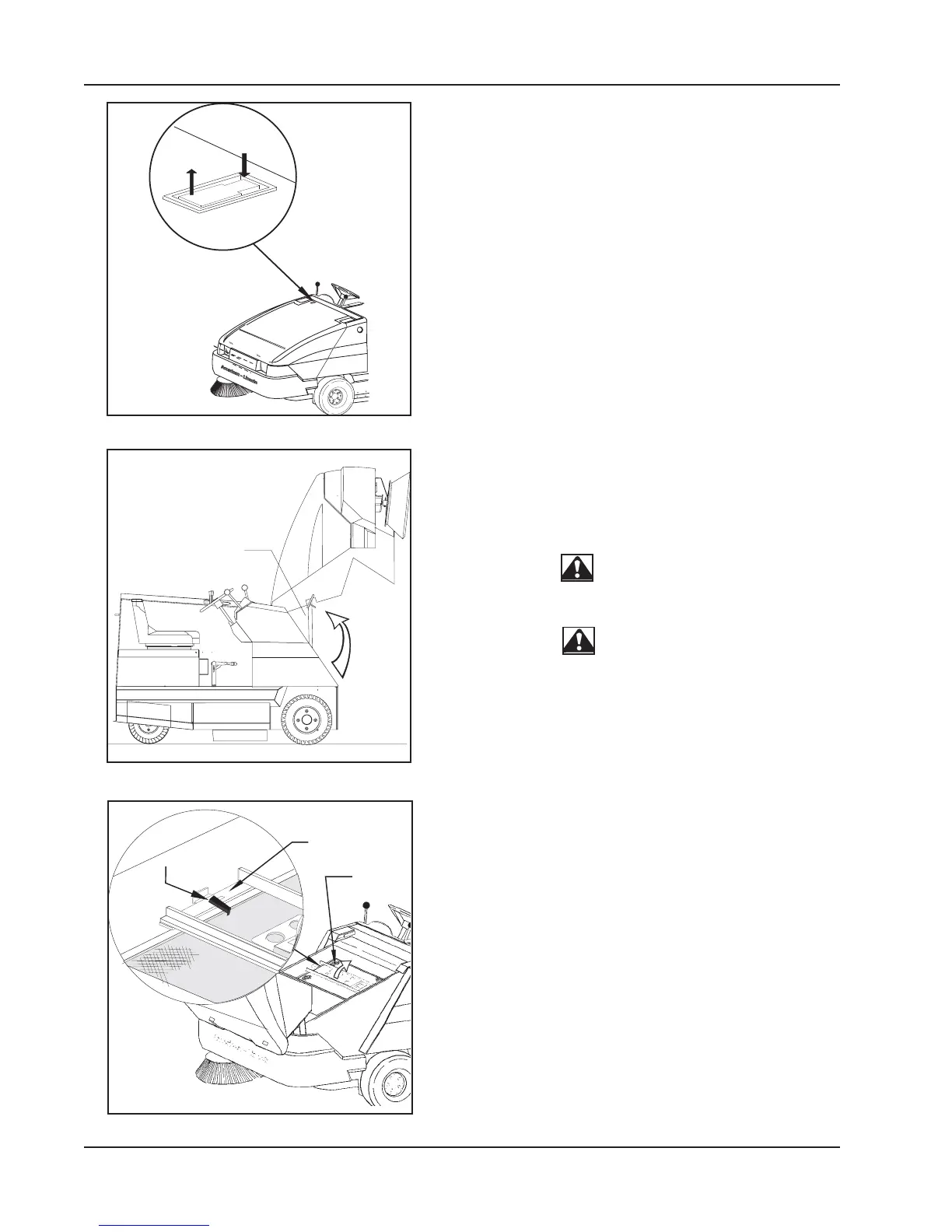
HOPPER SAFETY ARM (figure 27)
The hopper safety arm is located near the right front wheel
well. The safety arm will prevent the hopper from unexpect-
edly during service/maintenance.
dropping
WARNING
The Hopper Could Drop Unexpectedly And Cause injury.
Engage The Safety Arm Before Working Under Hopper.
WARNING
For Safety Always Empty Hopper Before Servicing.
TO ENGAGE THE SAFETY ARM:
1. Empty hopper
2. Set the parking brake.
3. Raise the Hopper.
4. Lift safety arm to engage the slot on the hopper
frame.
5. When work has been completed, replace the
safety arm to the stowed position.
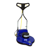
FILTER PANEL LATCH (figure 28)
The filter panel is located in the hopper filter compartment
and will need to be removed periodically for cleaning or
replacement. Removal of the filter panel requires no tools.
The hopper cover must be opened to gain access to the
filter compartment. The panel filter is held in place by a
hinged frame and latch.
To remove the panel filter, lift and turn the handle and lift the
hinged frame.
The panel filter can now be lifted out and cleaned or re-
placed (See Filter Cleaning instructions in this Manual). To
install the replacement panel filter, lower the frame , turn,
and lower the handle clockwise to lock the filter in place.
SWEEPER CONTROLS/INSTRUMENTS
FILTER
PANEL
LATCH
LIFT
FRAME T
REMOVE
FILTER
C0529a1
LIFT AND
TURN
LATCH
HOPPER
SAFETY ARM
TO
ENGAGE
C-0526
P
R
E
S
S
L
IF
T
A
N
D
T
U
R
N
PRESS
LIFT AND
TURN
C-0528A FIGURE 26
C-0526 FIGURE 27
C-0529A-1 FIGURE 28