DE-3000 IOI 7-17
All rights reserved © ALTRONIC, LLC 2017
2
1.0 OVERVIEW
1.1 For help locating subjects in this document, a section index is provided on page 61.
A glossary of technical terms begins on page 58.
1.2 The Altronic DE-3000 controller system is an electronic, microprocessor-based
system designed to sense various analog and digital input points to control and
monitor industrial compressors. The system is field-programmable using a PC
and the supplied terminal program and contains a non-volatile memory to store
the setup. Serial communications provide an interface to PC’s, PLC’s, modems
and satellite uplinks for remote communication. An LCD display shows system
status, programmed engine/motor and compressor parameters and channel la-
bels. A front-mounted keypad serves as the user interface. The DE-3000 pro-
vides for both the safety shutdown functions needed to prevent unnecessary
damage to remotely-operated equipment and the closed-loop automatic control
functions needed to optimize their efficiency of operation. The DE-3000 also
provides for remote data acquisition and supervisory control in a compact, low
cost package for industrial compressor applications. The optimization strate-
gies available for the management of compressor throughput include automatic
prime mover speed setting as well as capacity control. On rotary screw compres-
sors, capacity control can be done via suction throttling, or using an internal
gas bypass technique employing poppet valves, turn valves or slide valves. On
reciprocating compressors, capacity can be controlled using external gas bypass
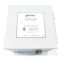
loops or pressure regulation techniques. A wide range of output options, includ-
ing both analog current loops and digital outputs, are provided to interface with
the large variety of actuation systems currently in use. In addition, automatic
load limiting based upon prime mover power capabilities or other application
specific limitations, such as cooling capacity, are readily implemented. There
are also AUTO START and OEM ENGINE CONTROL options that are enabled
using the terminal program.
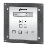
1.3 The system has three main parts: a panel-mounted Display Module (DE-3000),
a Power Supply Module (691122-1), and a Terminal Module (691171-1). These
components are interconnected by means of Cable assembly (693115-1). An
additional terminal board may be added for 30 extra channels (691171-2) or 15
extra channels (691175-2). This increases the channel selections from 1-30 to
1-60 or 1-45 respectively.
2.0 DISPLAY MODULE
2.1 The Display Module serves as the user interface for the DE-3000 system. It is in
a 6.5" x 6.5" panel-mounted enclosure and consists of an alphanumeric backlit
LCD display, a 16-key front-mounted keypad, DB-25 D-Sub and DB-9 D-Sub
connectors and five pairs of serial port indicators.
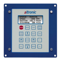
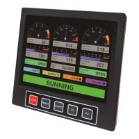
Two DE-3000 models are available and their displays are compatible with each
other, although they have a few functional differences. The ‘classic’ display is
4x20 characters, and the “new” display features 128x64 multi-color graph-
ics. The larger display uses the top line to further annunciate the engine status
“RUNNING, TIMERS ACTIVE, FIRST FAULT,” etc. The home screen, typical of
the 4x20 display, appears at the bottom of the larger display. It also incorpo-
rates a graphing capability which replaces the original bargraph feature. Color
backlighting has been added to the new display. The backlight color changes,
e.g., green for RUNNING, yellow for TIMERS ACTIVE and red for STOP/FAULT
condition, to indicate the status of the machine.
2.2 The keypad is a sealed membrane unit that contains the familiar STOP, RESET
and TEST keys as well as other keys used to navigate through channel status and
description, view process screens, and to edit the configuration.
2.3 The LCD displays a HOME SCREEN that displays a status line, the speed, the
suction pressure and the discharge pressure. Pressing the VIEW CHANNEL key
displays the channel number, its timer status, analog value (if applicable) and
the corresponding 20-character user defined label.
NOTE: IF POSSIBLE, KEEP THE ORIGI-
NAL SHIPPING CONTAINER. IF FUTURE
TRANSPORTATION OR STORAGE OF THE
CONTROLLER IS NECESSARY, THIS CON-
TAINER WILL PROVIDE THE OPTIMUM
PROTECTION.
WARNING: THE CONTROLLER SYSTEM
MUST BE CONFIGURED PRIOR TO USE
ON A COMPRESSOR SYSTEM. REFER-
ENCE THE PROGRAMMING INSTRUC-
TIONS (PAGE 53) FOR INSTRUCTIONS
DESCRIBING HOW TO CONFIGURE THE
CONTROLLER FOR THE SPECIFIC AP-
PLICATION. VERIFY THE PROGRAM IN
NONVOLATILE MEMORY (THE EEPROM)
PRIOR TO STARTING THE SYSTEM. RE-
FER TO SECTION 10.0 ON HOW TO VIEW
THE CURRENT CONFIGURATION.
WARNING: DEVIATION FROM THESE
INSTRUCTIONS MAY LEAD TO IMPROP-
ER ENGINE OPERATION WHICH COULD
CAUSE PERSONAL INJURY TO OPERA-
TORS OR OTHER NEARBY PERSONNEL.