DE-3000 IOI 7-17
All rights reserved © ALTRONIC, LLC 2017
36
16.0
VIEWING THE TIME AND DATE OF THE FIRST FAULT
16.1 The DE-3000 controller system “stamps” the time and date occurrence of the
first fault. To view the time and date of the first fault, press the F2 key after a
fault occurs but before reset is initiated. The time and date of the first fault will
be displayed. If no key is pressed for 10 seconds, the display will revert to the
first fault screen. Press the ESC key to return to the current home screen.
TIME AND DATE OF
THE FIRST FAULT.
TIME: 3:10 PM
DATE: 03-25-2012
RUNNING
17.0
CONTRAST RATIO ADJUSTMENT (CLASSIC DISPLAY ONLY)
17.1 The LCD contrast ratio is set at the factory for optimum contrast over a large tem-
perature range. It may be necessary however to make slight adjustments to the LCD
contrast ratio because of aging and or extreme temperature changes. The contrast
ratio potentiometer (TP1) is located on the back of the Display Module as shown in
the drawings section. Use an adjusting tool and turn the potentiometer clockwise to
lighten the contrast ratio or counterclockwise to darken the contrast ratio.
To set the potentiometer back to the factory setting: with the Display Module
at an ambient temperature of approximately 65°F to 77°F (18°C to 25°C), turn
the potentiometer clockwise until the display contrast ratio is almost too light
to read. Turn the potentiometer counterclockwise 3 to 3-1/2 turns. The display
should now be at a desirable contrast ratio.
18.0
DATA LOGGING AND COMMUNICATION OPTIONS
18.1 The DE-3000 controller system contains a data logging feature. Data logging
collects information from the system and keeps track of, or logs, that informa-
tion over a period of time. That data is then available through a PC or PLC at
port 1, the RS-232 port or port 3, the RS-485 port.
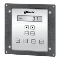
18.2 NODE NUMBER
The node number is the address of the controller being contacted. This number
is programmed by the terminal program and can be viewed or edited in the menu
screen, refer to section 15.14. A two-digit number from 01 to 99 can be used.
18.3 COMMUNICATIONS PARAMETERS
The following must be set in the PC or PLC to communicate with the controller
system:
• Baud Rate: 9600
• Data Bits: 8
• Stop Bits: 1
• Parity: None
18.4 The data logging memory can retain a total of 100 records before writing over
the oldest information. The most current data is always record number one; the
next most current is number two, etc. The oldest information, record 100, is lost
when a new record is written. The logging period is the time between data logs
and can be set from 5 minutes to 999 minutes. The logging period must be set
in the terminal program. Reference the programming instructions (section 30.0)
to set the logging period. So, for example, if the logging period is set for 60
minutes and there are 100 records, it would take 100 hours or 4.16 days before
any logged data was overwritten.
A new record is also written when a first fault occurs. If the first fault occurs
between the logging period, the first fault record will be record number one and
the next scheduled record will be number two.
TIME AND DATE OF
THE FIRST FAULT.
TIME: 3:10 PM
DATE: 03-25-2012