DE-3000 IOI 7-17
All rights reserved © ALTRONIC, LLC 2017
3
2.4 The keypad, along with the LCD display, are used to navigate through channel
status and descriptions, view process screens, and to view or edit the system’s
configuration. The
↑
UNITS or
↓
UNITS or the
→
TENS or
←
TENS keys are used
to access channels by increasing or decreasing the channel numbers by one or
by ten with each key press. Pressing the NEXT key advances the display to the
next screen or item. All menu adjustments are saved in non-volatile EEPROM
memory by pressing the ENTER key. The EEPROM memory retains the current
configuration during normal operation, after compressor shutdown and a system
power-down.
2.5 Five pairs of LED’s are provided on the back of the Display Module for trouble-
shooting purposes, one Receive (RX) and one Transmit (TX) LED for each port.
The TX LED will flash when the Display Module is transmitting serial communi-
cations on the labeled port. The RX LED will flash when the Display Module is
receiving serial communications on the labeled port.
2.6 Ports 4 and 5 are located on the display board.
3.0 POWER SUPPLY MODULE
3.1 The Power Supply Module is made to be rail-mounted and is the interface be-
tween the Terminal and Display Modules and to other systems. It typically plugs
directly into the Terminal Module using the DB-25 connectors and is held to-
gether with screws and screw locks.
3.2 The Power Supply Module accepts up to four industry-standard, commercially-
available 0.6 inch plug-in Output Modules. The Output Modules provide a means
of using the DE-3000 controller safety shutdown system status to interface with
other systems on the engine/motor and compressor. A typical application would
be as a relay or solenoid coil driver. T he Output Modules are optically isolated,
solid-state switches which are isolated from power supply minus and engine
ground. The Output Modules will be in the open (de-energized) condition when
the unit is not powered.
Outputs 1 and 2 can be software-configured for either normally-open (N/O) or
normally-closed (N/C) operation and have an LED indicator associated with them.
Outputs 3 and 4 are pre-programmed normally-open for use with the optional
OEM Engine Control or Auto start feature. If an Output Module is programmed for
normally-closed (energized for run), the LED will be ON in the normal run condi-
tion and OFF for a fault condition. For Normally-open configured modules the LED
will be OFF for normal run condition and turn ON for a fault condition.
The standard Output Module outputs use the top row of the dual 16-position
terminal strip which is marked OUT 1 through OUT 4. Each of these outputs
are fused with a replaceable 6.3 amp slow-blow fuse, Altronic P/N 601653.
In addition to accepting industry-standard Output Modules, a custom Altronic
Output Module P/N 691124 is available for tripping ignition powered CD fuel
valves and shorting CD ignition shutdown leads upon a fault. When making use
of OEM Engine Control, outputs 1 and 2 will not be wired to trip the fuel and ig-
nition valves. When both functions are required, two of these modules are used
as follows: OUT 1 slot must be used to trip the fuel valve, and OUT 2 slot must
be used to short the ignition. If 12-24Vdc is lost to the DE-3000 annunciator
system, the custom Output Modules will trip the fuel valve and short the igni-
tion shutdown lead. This mimics the “fail-safe” operation of a normally-closed
Output Module and therefore the LED will be ON in the normal run condition
and OFF for a fault condition. In programming the system, these modules are
identified by using the IGN/FUEL selection. Terminals IGN+ and IGN− are used
to connect the shutdown lead, and FV1 and FV2 are used for the CD fuel valve.
A capacitor is included in the Power Supply Module to supply the energy to trip
the fuel valve.
3.3 The 12-24Vdc power for the DE-3000 system is applied to the power supply
terminals marked (+) and (−) 12–24Vdc INPUT POWER. A 6.3 amp replaceable
slow-blow fuse protects the system from over-currents, and a power LED lights
when power is applied to the system.
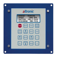
CLASSIC DISPLAY
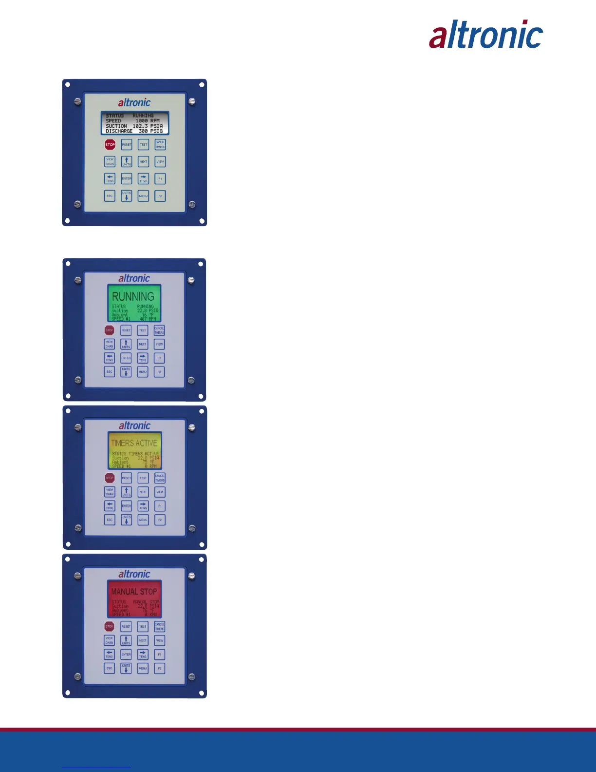
NEW DISPLAY