DE-3000 IOI 7-17
All rights reserved © ALTRONIC, LLC 2017
5
housing with a 5/8"-18 UNF threaded body, and a Packard Electric Metri-Pack
connector. During configuration the standard calibration for the 691202/203-300
sensor is selected as dEG1 and the standard calibration for the 691212/213-450 is
selected by choosing dEG2. The three wires from the transducer are: +5 volt excita-
tion, temperature output voltage, and minus return. These wires connect directly to
the Terminal Module using cable assembly P/N 693008-x.
4.7 THERMOCOUPLE INPUTS
The Terminal Modules can accept industry-standard type J or K thermocouples
on inputs 01–60. Automatic cold junction compensation is built-in. The units
can be configured to °F or °C. Both a high and low setpoint is associated with
each channel. The monitor can read type J thermocouples between -76°F and
+1382°F (-60°C and +750°C) and type K thermocouples between -76°F and
+1472°F (-60°C and +800°C).
4.8 N/O and N/C INPUTS
The inputs can also accept standard normally-open and normally- closed con-
tacts. For normally-open input, place the wire between the corresponding in-
puts. Ground the connection to cause a fault. Similarly, for normally-open, wire
the sensor in a normally-closed connection and open it to cause a fault.
4.9 4-20mA inputs
The terminal module can accept 4-20mA inputs by selecting the internally-
connected 200-ohm resistors, creating a termination voltage of .8 to 4.0 volts.
The jumper wires between the + and – terminals for that channel must be con-
nected for proper operation.
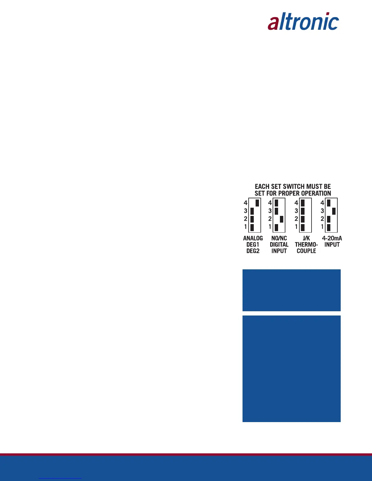
4.10 For each input, the corresponding CHANNEL SWITCH must be set according
to the input type. Switches are turned ON by moving them toward the ANALOG
OUT labeling.
4.11 Digital outputs 1 through 8 are pilot-duty, and turn on to common ground when
closed. Outputs 1 through 8 are rated at 500mA, 60V. See FIG. 8 for wiring details.
5.0 MOUNTING
5.1 DISPLAY MODULE
Mount the Display Module inside a control panel or to a suitable flat surface so
that the display is at a convenient viewing height. A drilling template and mount-
ing dimensions are provided.
5.2 POWER SUPPLY MODULE
Mount the Power Supply Module in the panel either on the bottom or the side of
the main panel. The Power Supply Module is made to be rail-mounted onto com-
mercially available 32 or 35mm DIN mounting rails. It is also made to plug directly
into the Terminal Module using the DB-25 connectors and is held together with
screws and screw locks. Two end brackets P/N 604199 should be used to keep
the modules from sliding off the ends of the mounting rail.
Alternatively, the Power Supply Module and the Terminal Module can be mount-
ed separate from each other on the DIN mounting rails but in the same panel;
in this case, a DB-25 male/female cable such as P/N 693115-1 is used to elec-
trically connect these modules. The operating temperature range of the Power
Supply Module is −31°F to +176°F (−35°C to +80°C).
5.3 TERMINAL MODULE
Mount the Terminal Module either on the bottom or the side of the main panel.
The Terminal Module and Power Supply Module can be rail-mounted onto com-
mercially available 32 or 35mm DIN mounting rails. The Terminal Module plugs
directly into the Power Supply Module using the DB-25 D-Sub connectors and
is held together with screws and screw locks. Two end brackets P/N 604199
are used to keep the modules from sliding off the ends of the rail. The Terminal
Module and the Display Module are electrically connected with a DB-25 male/
female cable, 693115-x series or equivalent. The operating temperature range
of the Terminal Module is −31°F to +176°F (−35°C to +80°C).
NOTE: AVOID MOUNTING THE UNIT
WITH THE LCD DISPLAY FACING DIRECT
SUNLIGHT. THE DISPLAY OPERATING
TEMPERATURE RANGE IS −13°F TO
+149°F (−25°C TO +65°C).
IMPORTANT: PRESSURE TRANSDUCERS
WILL WITHSTAND OVERLOADS AS HIGH
AS 1.5 TIMES RATED PRESSURE. IF THE
OVERLOAD RATING IS EXCEEDED, FAIL-
URE MAY OCCUR. PRESSURE FLUCTUA-
TIONS OCCUR IN MOST RECIPROCATING
SYSTEMS; PICK THE TRANSDUCER
WITH A RATING HIGH ENOUGH TO PRE-
VENT OVERLOAD BY PEAK PRESSURES
OF PULSATIONS. IT IS RECOMMENDED
THAT A PRESSURE SNUBBER BE USED
WHICH WILL REDUCE THE PEAK PRES-
SURE APPLIED TO THE TRANSDUCER.
THE LIFE OF THE TRANSDUCER WILL BE
EXTENDED WITH THE USE OF A SNUB-
BER OR PULSATION DAMPENER.