DE-3000 IOI 7-17
All rights reserved © ALTRONIC, LLC 2017
61
MODBUS ADDRESS LIST:
ADDRESS DESCRIPTION OF FUNCTION
40001 NULL
40002 Hourmeter; range from 0-65535
40003 NULL
40004 STATUS FAULT (01-60) FOR FAULT CHANNEL 01-60
S01 = 151, S02 = 152, Overcrank = 165, serial fault = 166
00 = STOP, 254= timers active, 255 = running
40005 Output status BIT0 = OUT1, BIT1 = OUT2, BIT2 = OUT3, BIT3=OUT4
40006 Fault Status, 0=NA, 1=LOW FAULT, 2=HIGH FAULT
40020 Digital output status for terminal board #01
40021 Digital output status for terminal board #02
40030 —
40069
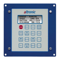
The ASCII characters of what is contained on the display of the
DE-3000. The upper part of the register displays the first character
followed by the low part of the register as the next character. This
may be used for MMI/MIDAS applications.
40080 Writable register for the keypad input. Use function 6 to perform
the write. Section 18.16 describes the values for each key press.
This register, along with 40030-40069, may be used in conjunc-
tion with a MMI/Red Lion to press keys on the keypad.
40090 —
40149
40090 = channel 01, 40091 = channel 02…
40200 Writable register for PID setpoint #1
40201 Writable register for PID setpoint #2
40202 Indicates the time remaining for the test timer. The value is (-1) if
not in test mode.
40250 RPM; range from 0 - 9999 (S01)
40251 RPM; range from 0 - 9999 (S02)
40255 Analog output in percent (A01)
40256 Analog output in percent (A02)
40257 Analog output in percent (A03)
40258 Analog output in percent (A04)
40300 —
40449
Decimal point location for channel 001—150, range from 0
to 3. 0 = no decimal place, 1 = 1 decimal place. Etc.