DE-3000 IOI 7-17
All rights reserved © ALTRONIC, LLC 2017
9
7.0 HAZARDOUS AREA OPERATION
7.1 The DE-3000 system is CSA-certified for CLASS I, DIVISION 2, GROUPS C and
D areas when mounted in a suitable enclosure.
In addition, the following requirements must be met (refer to NFPA standard no. 493):
•
The low voltage sensor switch wires within the panel enclosure must
be kept at least two (2) inches away from other wiring. Run the sensor
switch wires leaving the panel in a separate conduit from all other wiring
and keep them separate
•
Wiring to the sensors must have a grade of insulation capable of with-
standing an AC voltage of 500 volts RMS.
•
Sensor wires must be run in separate conduits and junction boxes from high
voltage wires such as ignition, fuel valve, and other high voltage wiring.
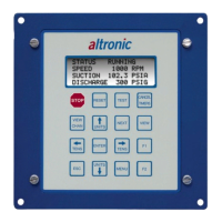
8.0 KEYPAD DESCRIPTION
8.1 The DE-3000 controller Display Module contains a sixteen-key sealed mem-
brane keypad which is used to stop, reset and test the system. The user can also
view process information screens, view channel specifics, cancel timers, and
view and edit pertinent operating parameters.
8.2 STOP key is used for a manual stop condition. By pressing the STOP key, the
controller activates the configured output modules in the power supply.
8.3 RESET key clears all past faulted points and resets all input and output timers
to their preset values.
8.4 TEST key disables the output modules and allows the user to fault or test the input
sensors. Every time the test button is pressed, the test timer resets to its preset value.
8.5 CANCEL TIMERS key cancels all timers.
8.6 VIEW CHAN key allows the user to view the status of any input channel and its
user defined label. Pushing the VIEW CHAN key after a fault will display the
faulted channel and current value.
8.7 NEXT key allows the user to view the CAPACITY CONTROL and RPM SETPOINT
CONTROL screens from the home screen. From the VIEW screen, allows the
user to view the next process information screen. From the MENU screens, the
next value to be edited.
8.8 VIEW key allows the user to view the status of the digital outputs 1 though 8 follow-
ing the first depression. If the digital output is on, the number of that output will be
viewable. Pressing the VIEW key a second time will open the graphing mode.
8.9 ENTER key is used to accept a selection and to save a new value in memory.
8.10 ESC key enables the user to exit any view channels, information or menu screens
at any time and return to the previous screen without changing programmed
values.
8.11 MENU key allows the user to enter the edit menu. The global timers, input class
output assignment, output configuration and the time and date may be viewed
and adjusted using the MENU key.
8.12
↑
UNITS/
↓
UNITS keys increase or decrease values by one. The
→
TENS/
←
TENS
keys increase or decrease values by ten. They are used to increase or decrease
channel numbers, timers and to move the pointer in the menu screen.
8.13 F1 - Function key displays the analog input and output channels.
8.14 F2 - From the RUNNING home screen; used to initiate the cool-down timer.
After a fault, displays the time and date of the 1st fault.
WARNING: SUBSTITUTION OF COMPO-
NENTS MAY IMPAIR INTRINSIC SAFETY
AND/OR SUITABILITY FOR CLASS I, DIV.
2, GROUPS C AND D. DO NOT DISCON-
NECT EQUIPMENT IN DIV. 2 ENVIRON-
MENT UNLESS POWER IS SWITCHED
OFF OR THE AREA IS KNOWN TO BE
NON-HAZARDOUS.